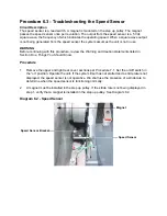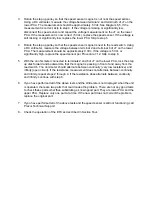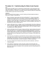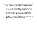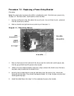
Procedure 6.6 - Troubleshooting the Lift System
Note:
The lift motor is disabled when the EFX is not being used. The speed sensor must detect motion
in order for lift operation to be enabled. In the following procedures, when lift motor movement is
being tested the stairarms must be in motion. Before performing this procedure, ensure that the
speed sensor is operating normally per Procedure 6.3.
1.
If an error 42 occurs skip to step 3. If the lift’s physical position does not agree with the lift’s
level display continue with step 2.
2.
Access the Production Check Mode per Procedure 2.4 The lift will operate to level 8. If the
lift level display does not increment as the lift moves, skip to step 3. If the lift level
increments as the lift moves, re-calibrate the lift per Procedure 5.2. If re-calibration does not
correct the problem, continue with step 3.
3.
Set the on/off switch in the “off” position. Remove the lift position cable connector from the
lower PCA. Using an ohmmeter, measure between terminal 1 (brown wire) and terminal 3
(blue wire). The measurement should be approximately 1K
Ω
.
4.
Using an ohmmeter, measure between terminals 1 and 3 (green and orange) of the J5
connector and measure between 1 and 4 (green and brown) of the J5 connector. The two
measurements should total approximately 1K
Ω
. If any of the readings are open (
∞
) or
significantly high, check the lift motor cable and connectors. Repair any wires or
connections that are bad. If the cable and connectors are good, continue with step 5+.
5.
Set the on/off switch in the “off” position. Remove the F1 lift fuse (2 amp slow blow) fuse
from the lower PCA. Measure the fuse with an ohmmeter. The measurement should be 1
Ω
or less. If the fuse is good, re-insert the fuse and skip to step 9. If the fuse is open (
∞
) or
significantly high, replace the fuse. Before operating the lift motor it is necessary to perform
a continuity test on the lift motor.
6.
Remove the J4 connector from the lower board. Using an ohmmeter, measure between
terminals 1 and 2 (yellow and red) between terminals 1 and 3 (black and yellow) and
between terminals 2 and 3 (red and black). The measurements should be approximately
14.7
Ω, 14.3Ω
and 29
Ω,
respectively. If any of the measurements are significantly low,
replace the lift motor. If any of the readings are open (
∞
) or significantly high, check the lift
motor cable and connectors. Repair any wires or connections that are bad. If the cable and
connectors are good, continue with step 9.
7.
Re-insert the lift power connector in the lower PCA. Set the on/off switch in the “on” position.
Using an AC voltmeter, monitor the voltage between terminals 1 and 2 (white and red wires)
of the lift power connector. Enter the manual program and press the
INCLINE
S
key. The
measurement should be approximately 120 Vac (line voltage). If the voltage is present and
the lift motor moves normally, skip to step 10. The voltage will only be present until such
time as an error occurs. If line voltage is not present skip to step 11. If line voltage is
measured but the motor does not move, replace the lift motor.
Summary of Contents for EFX EFX 5.23
Page 79: ...Block Diagram 8 2 5 23 5 25...

