

6.
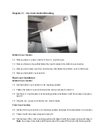
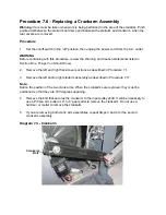
Remove the four bolts, two front and two rear, that fasten the lower portions of the right
outrigger to the frame.
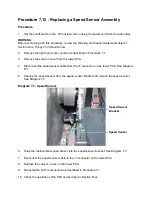
7.
Carefully slide the right outrigger away from the frame to expose the data cables and
connector module at the bottom front portion of the right outrigger.
8.
Disconnect the upper data cable from the connector module.
9.
Tape one end of the replacement data cable to the display end of the existing upper data
cable. Carefully pull the existing upper data cable out of the hole in the bottom end of the
right outrigger, as you feed the replacement data cable into the upper end of the right
outrigger. Stop when the replacement data cable appears out of the hole in the bottom of
the right outrigger.
10. Remove the tape fastening the two data cables and discard the old data cable.
11. Connect the new data cable to the connector module. Slide the right outrigger into its
mounting position and feed the upper end of the new data cable into the opening in the
upright support.
12. Hand start but do not tighten the four lower and three upper right out rigger mounting bolts
removed in steps 5 and 6. Tighten these seven bolts after all have been hand started.
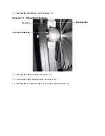
13. Place the ferrite, removed in step 4 around the data cable and heart rate cable and snap it
into place.
14. Reconnect the data cable and heart rate cable to the rear of the display assembly and set it
in its mounting position on the upright support.
15. Fasten the display assembly to the upright support with the bolts removed in step 2.
16. Check operation as described in Section Four.
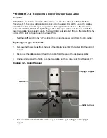
Replacing the Lower Data Cable
17. Remove the three screws from the rear of the display assembly that fasten it to the upright
support.
18. Disconnect the data cable and heart rate cable from the rear of the display assembly.
19. Remove the three bolts that fasten the upper end of the tight outrigger to the upright
support.
20. Remove the four bolts, two front and two rear, that fasten the right outrigger to the frame.
21. Carefully slide the right out rigger away from the frame to expose the data cables and
connector module at the bottom front portion of the right outrigger.
22. Disconnect the lower data cable from the connector module.
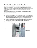
Summary of Contents for EFX EFX 5.23
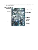
Page 79: ...Block Diagram 8 2 5 23 5 25...


