

9.
Remove the input pulley belt and place the replacement input pulley belt in it’s place on the
step up pulley assembly.
10. Set the step up pulley assembly with the step up and input belt at its mounting position in the
drive unit. Replace the tensioning bolts, locking tabs and brackets removed in step 8.
Thread the left and right tension bolts into the step up pulley shaft.
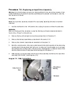
11. Slide the step up and input belts onto the input drive assembly as you set the input drive
assembly in its mounting position in the drive unit.
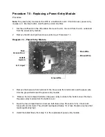
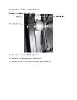
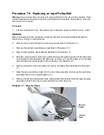
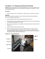
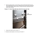
12. Slide the pillow block bearings onto the input pulley shaft with the stamping on one pillow
block bearing on top and the stamping on one pillow block bearing on the bottom. See
Diagram 7.5.
13. Thread and hand tighten the pillow block mounting bolts into the drive weldment upright.
Torque the pillow block mounting bolts to 120 inch pounds (10 foot pounds).
14. Tighten the right and left hand tension bolts and using a stout screwdriver as a lever, press
the idler pulley to the right. to remove most of the slack from the belt, tighten the idler puller
axle bolt.
15. Tighten the right and left hand step up belt tension bolts and the idler pulley mounting bolt to
the settings marked in step 5.
16. Verify the tension of the belts per Procedure 5.2.
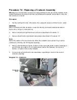
17. Replace the crankarm(s) per Procedure 7.6
18. Replace the stairarms per Procedure 7.17.
19. Check drive input adjustment per Procedure 5.4.
20. Replace the top, left and right cover sections per Procedure 7.1.
Summary of Contents for EFX EFX 5.23
Page 79: ...Block Diagram 8 2 5 23 5 25...


