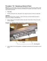

9.
Remove the tubular metal insert from the lift motor mount and retain for later use. Remove
the lift motor.
10. Set the replacement lift motor in its mounting position and slide the tubular metal insert
removed in step 9 into the lift motor mount. Fasten the lift motor with the bolt removed in
step 7.
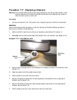
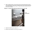
11. Reconnect the lift motor connector and replace the frame ground.
12. Calibrate the lift motor per Procedure 5.3.
13. Set the rear incline cover section in its mounting position. Move the lift motor into place with
the lift nut in between the tines of the yoke. Fasten the lift nut to the yoke with yoke mounting
bolts removed in step 5.
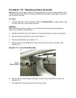
14. Fasten the rear incline cover section with the two bottom screws removed in step 2.
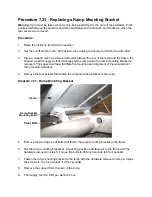
15. Set the top retaining bracket in its mounting position and fasten it with the screws removed
in step 5.
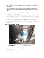
Diagram 7.25 - Lift Motor Mounting
16. Set the front incline cover section in its mounting position and fasten it with the eight screws
removed in step 2.
17. Thoroughly, test the EFX per Section Four.
Lift Motor Connector
Frame Ground
Summary of Contents for EFX EFX 5.23
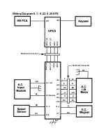
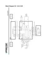
Page 79: ...Block Diagram 8 2 5 23 5 25...


