b. If the hand pulse sensors and/or electrical contacts do not have corrosion, con-
tinue procedure.
8. Verify that the HHHR handlebar pulse sensor cable is not damaged and that it is cor-
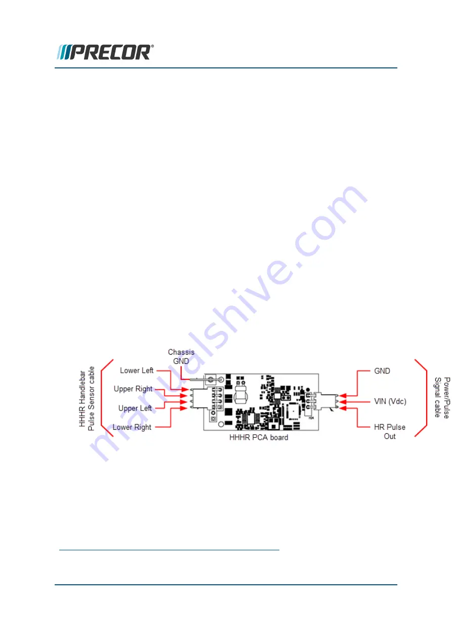
rectly installed. Verify the four HHHR PCA pulse sensor input connector pins ( left top,
left lower , right top , and right lower) are attached to their respective handlebar pulse
sensor terminal, (see HHHR PCA schematic below). Also inspect the cable for any
visual cable wire damage or connector pin damage.
a. If this did not fix the problem, verify that each one of the four pulse sensor wires
( left top, left lower , right top , and right lower) has connector pin-to-pin con-
tinuity, use a multimeter to measure the cable connectors pin-to-pin resistance.
b. If the wiring is correct, continue procedure.
9. Verify that the HHHR board has the correct operating input voltage. Remove the
Power/Pulse Signal cable from the HHHR PCA 3-pin connector and measure the Vdc
voltage between the VIN (pin 2) and the GND (pin 1) pins. The voltage should meas-
ure between 4.5 and 5 Vdc (see HHHR PCA schematic below).
a. If no voltage, make sure the Power/Pulse Signal cable 3-pin plug is correctly
connected to the
UPCA
1
board connector. Remeasure Vdc, if no voltage,
Verify the cable is not damaged by checking the pin-to-pin wire continuity, If the
cable is not damaged, replace the UPCA board or console.
b. If there is correct Vdc input voltage and the HHHR does not function correctly,
continue procedure.
10. If the above procedures do not correct the problem, replace the heart rate HHHR PCA
board.
Wireless Heart Rate Does not Work
1. Grasp the handlebar HHHR pulse sensors and verify that the handheld HHHR feature
is functioning correctly, showing a correct heart rate.
1
Upper PCA board
Contact Precor Customer Support at support@precor.com or 800.786.8404 with
any questions.
Page 208
7 Troubleshooting
System Troubleshooting Procedures


