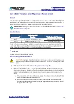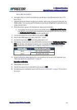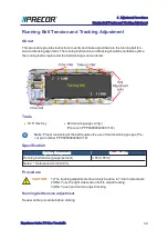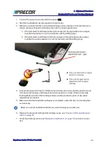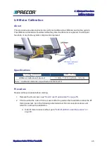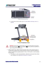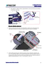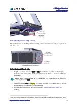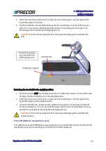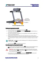
motor pulley mechanism.
6. Re-tighten the four motor mount fasteners and torque to specification 204 in-lbs (17 ft-
lbs, 23 N-m).
7. Reinstall drive belt. Place Drive Belt onto the the motor pulley and walk the belt onto the
Roller pulley. You can use your free hand to move the motor flywheel to rotate the motor
pulley and drive belt.
8. Place the tension gauge onto the belt and remeasure the tension.
a. .f the tension measurement does not meet the tension Calibration Belt Tension
specification, repeat the tension adjustment process until the tension does meet
the Calibration Belt Tension tension specification.
9. Connect the power cord and switch the input power ON.
10. Run the treadmill speed at 3 mph (5 kph) for 1 minute.
11. Switch the input power OFF and unplug the power cord.
12. Remeasure the belt tension and verify that the tension meets the Verification Belt Ten-
sion specification. Recalibrate the belt tension if not within the Verification Belt Ten-
sion specification, see
"Belt tension calibration adjustment " on the previous page
.
Belt Condition
Verification Belt Tension
New
100-120 lbs (45-54 kgs)
Used
80-90 lbs (36-41 kgs)
13. Verify that the Drive Belt alignment is correct and has not moved out of alignment, see
"Drive belt alignment adjustment" on page 36
.
Operation verification
14. Reinstall the hood cover.
15. Connect the power cord and switch the input power ON.
16. Do the Operation Verification tests (see
"Operation Verification" on page 15
) and return
to service.
Experience Series 700 Line Treadmills
39
4 Adjustment Procedures
Drive Belt Tension and Alignment Adjustment
Summary of Contents for Experience TRM700-16
Page 1: ...Service Manual Experience Series 700 line TRM700 16 Base Treadmill 120 VAC and 240 VAC ...
Page 19: ...Experience Series 700 Line Treadmills 12 1 Introduction General Information ...
Page 104: ...Experience Series 700 Line Treadmills 97 5 Replacement Procedures Drive Belt Replacement ...
Page 172: ...Experience Series 700 Line Treadmills 165 8 Theory of Operation System Wiring Diagram ...
Page 174: ...Experience Series 700 Line Treadmills 167 8 Theory of Operation Exploded View Diagram ...
Page 175: ...Experience Series 700 Line Treadmills 168 8 Theory of Operation Exploded View Diagram ...
Page 176: ...Experience Series 700 Line Treadmills 169 8 Theory of Operation Exploded View Diagram ...
Page 177: ...Experience Series 700 Line Treadmills 170 8 Theory of Operation Exploded View Diagram ...
Page 178: ...Experience Series 700 Line Treadmills 171 8 Theory of Operation Exploded View Diagram ...
Page 179: ...Experience Series 700 Line Treadmills 172 8 Theory of Operation Exploded View Diagram ...
Page 181: ...Experience Series 700 Line Treadmills 174 8 Theory of Operation Parts List ...
Page 182: ...Experience Series 700 Line Treadmills 175 8 Theory of Operation Parts List ...
Page 183: ...Experience Series 700 Line Treadmills 176 8 Theory of Operation Parts List ...


