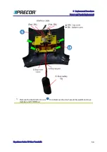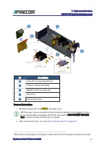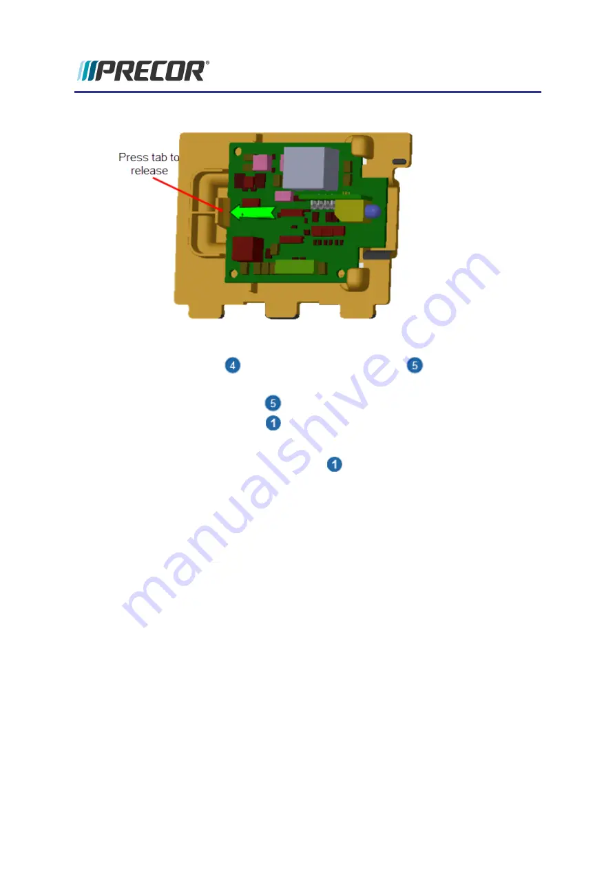
tab clip to remove.
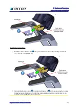
Installation Instructions
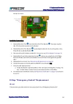
1. Reinstall the ASL PCA
board onto the ASL PCA Bracket
. Securely snap the
ASL PCA board into position on the bracket.
2. Reinstall the ASL PCA Bracket
by pressing the tabs into the mounting slots on the
Power Entry Assembly Bracket
.
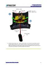
3. Reconnect the ASL interface cable RJ11 connector, see
4. Reinstall the Power Entry Assembly bracket
and secure using the four #3 Phillips
fasteners. Make sure that the wire cables are not pinched or damaged during install-
ation.
5. Reinstall the hood cover, see
"Hood Cover Replacement" on page 56
.
6. Connect the power cord and switch the ON/OFF circuit breaker ON.
7. Verify the ASL light operation:
a. Verify that the ASL light is Solid Blue. If the ALS light is Pulsing Blue, Pulsing Yel-
low, or Solid Yellow, resolve the issue and reset the ASL to Solid Blue.
8. Do the Operation Verification tests (see
"Operation Verification" on page 15
) and return
to service.
E-Stop "Emergency Switch" Replacement
About
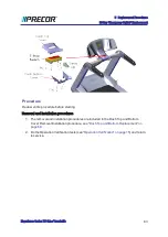
This procedure provides instruction to replace the E-Stop "Emergency Stop Switch".
Experience Series 700 Line Treadmills
82
5 Replacement Procedures
E-Stop "Emergency Switch" Replacement
Summary of Contents for Experience TRM700-16
Page 1: ...Service Manual Experience Series 700 line TRM700 16 Base Treadmill 120 VAC and 240 VAC ...
Page 19: ...Experience Series 700 Line Treadmills 12 1 Introduction General Information ...
Page 104: ...Experience Series 700 Line Treadmills 97 5 Replacement Procedures Drive Belt Replacement ...
Page 172: ...Experience Series 700 Line Treadmills 165 8 Theory of Operation System Wiring Diagram ...
Page 174: ...Experience Series 700 Line Treadmills 167 8 Theory of Operation Exploded View Diagram ...
Page 175: ...Experience Series 700 Line Treadmills 168 8 Theory of Operation Exploded View Diagram ...
Page 176: ...Experience Series 700 Line Treadmills 169 8 Theory of Operation Exploded View Diagram ...
Page 177: ...Experience Series 700 Line Treadmills 170 8 Theory of Operation Exploded View Diagram ...
Page 178: ...Experience Series 700 Line Treadmills 171 8 Theory of Operation Exploded View Diagram ...
Page 179: ...Experience Series 700 Line Treadmills 172 8 Theory of Operation Exploded View Diagram ...
Page 181: ...Experience Series 700 Line Treadmills 174 8 Theory of Operation Parts List ...
Page 182: ...Experience Series 700 Line Treadmills 175 8 Theory of Operation Parts List ...
Page 183: ...Experience Series 700 Line Treadmills 176 8 Theory of Operation Parts List ...


