For MYE displays.
l
Analog video power (at each display): - 30 dB to +20 dB RF power with a (+40 db C/N
(Channel to Noise ratio) .
l
Digital RF power (at each display): -5 dB to 0 dB.
Using an RF wall outlet
If a wall RF outlet is used to power several consoles in series for a row of equipment there is a
minimum RF power requirement at the outlet of +35 dB at +40 dB minimum channel to noise
ratio for analog video and a +25 dB for Digital video. RF signal strength of +35 dB can power
17 to 19 consoles in a single row when properly tapped out.
Internet Ethernet Requirements
It is recommend a dedicated CAT6 Ethernet feed to each equipment location.
Communication Requirements:
l
512Kb/s up
l
5-10Mb/s down
l
Switch Ports: 80, 123, 443
The P80 console uses a security token for communication to Precor servers. The security
token is a hash string that is sent with every API call from the FE’s to the Amazon Cloud. It ori-
ginates after the equipment is registered at the location. The P80 issues a ‘Call’ which returns
the registration token and the fitness equipment URL. Every event after that uses the URL and
the token to validate/authenticate communication with the Amazon servers and Preva Busi-
ness Systems (PBS).
All communication with our servers is currently done via outgoing (originating from the con-
sole) HTTPS sessions. The P80 utilizes
NTP
1
to set its clock and for synchronization. At no
time is Precor connecting to your network to "push" any data. The P80 initiates all data
requests.
.
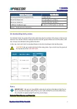
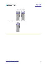
Treadmill Placement and Spacing Requirement
The minimum side to side spacing between treadmills is 20 in (0.5 m) and the minimum front to
back spacing is 78 in (2 m).
1
Network Time Protocol (NTP) is a networking protocol for clock synchronization between
computer systems over packet-switched, variable-latency data networks.
Experience Series 700 Line Treadmills
11
1 Introduction
General Information
Summary of Contents for Experience TRM700-16
Page 1: ...Service Manual Experience Series 700 line TRM700 16 Base Treadmill 120 VAC and 240 VAC ...
Page 19: ...Experience Series 700 Line Treadmills 12 1 Introduction General Information ...
Page 104: ...Experience Series 700 Line Treadmills 97 5 Replacement Procedures Drive Belt Replacement ...
Page 172: ...Experience Series 700 Line Treadmills 165 8 Theory of Operation System Wiring Diagram ...
Page 174: ...Experience Series 700 Line Treadmills 167 8 Theory of Operation Exploded View Diagram ...
Page 175: ...Experience Series 700 Line Treadmills 168 8 Theory of Operation Exploded View Diagram ...
Page 176: ...Experience Series 700 Line Treadmills 169 8 Theory of Operation Exploded View Diagram ...
Page 177: ...Experience Series 700 Line Treadmills 170 8 Theory of Operation Exploded View Diagram ...
Page 178: ...Experience Series 700 Line Treadmills 171 8 Theory of Operation Exploded View Diagram ...
Page 179: ...Experience Series 700 Line Treadmills 172 8 Theory of Operation Exploded View Diagram ...
Page 181: ...Experience Series 700 Line Treadmills 174 8 Theory of Operation Parts List ...
Page 182: ...Experience Series 700 Line Treadmills 175 8 Theory of Operation Parts List ...
Page 183: ...Experience Series 700 Line Treadmills 176 8 Theory of Operation Parts List ...

