background image

Cardio Theater Integrated Bracket Assembly Instructions

page 22

5

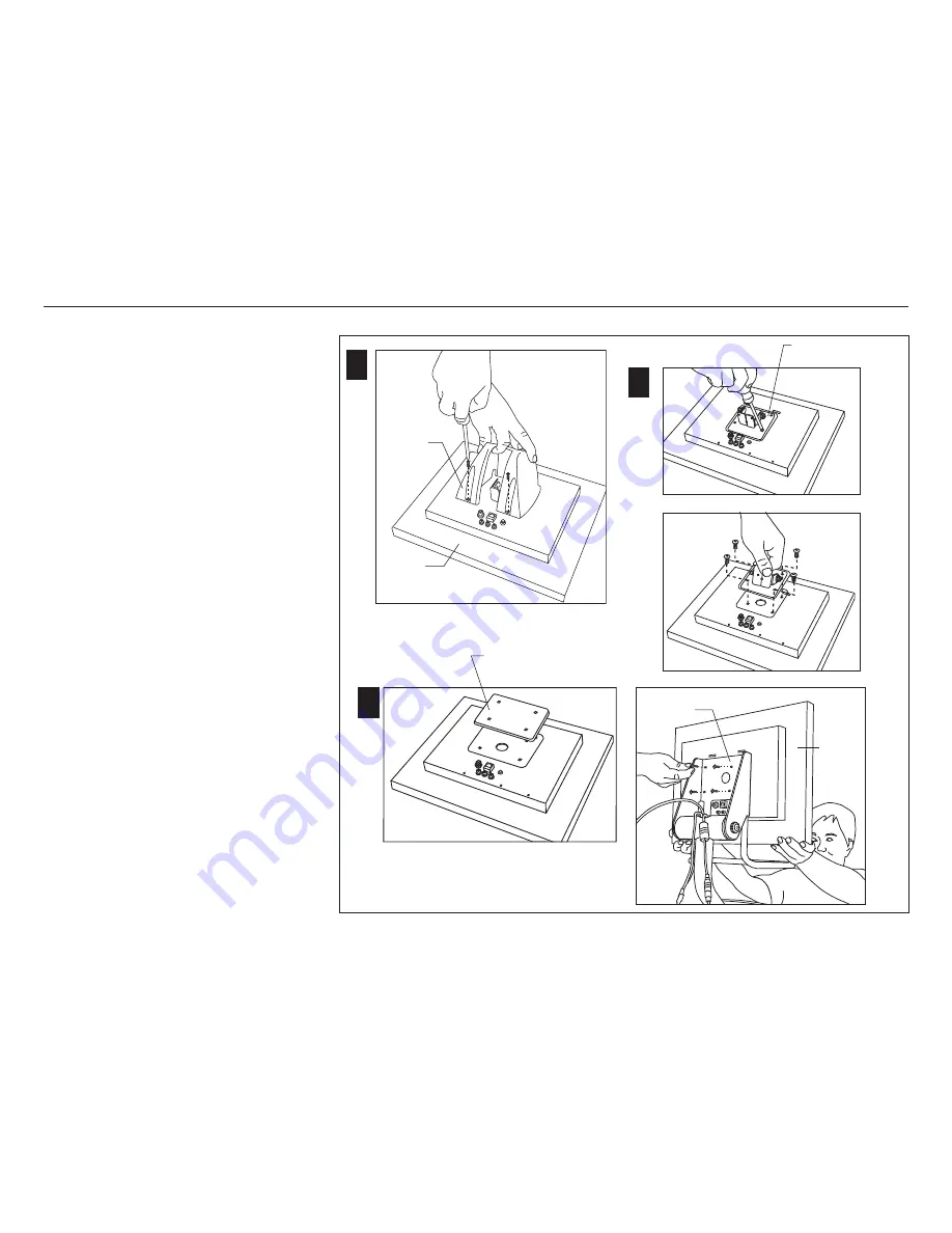
Attach the LCD Screen

Important: 

The screen spacer is used only for the

Cardio Theater PVS4/5/15 LCD Screen.

1.

To protect the LCD Screen for the next few
steps, place it screen side down on a clean
work surface.

Important:

 Use proper materials to protect the

LCD Screen while you remove the plastic cover
and metal mounting bracket from the backside
of the LCD Screen.

2.

Remove the plastic cover.

Use a Phillips-head screwdriver to remove
the two screws holding the plastic cover to
the LCD Screen. Discard the plastic cover and
the screws.

3.

Remove the metal mounting bracket.

Remove the four screws securing the metal
mounting bracket. Discard the mounting bracket
and the four screws.

4.

Retrieve four new Phillips-head screws
from the bracket assembly package.

Note

: Use the longer screws if attaching the

screen spacer with the PVS4/5/15 LCD Screen.

5.

Attach the LCD Screen to the bracket assembly.
If you have the Cardio Theater PVS4/5/15 LCD
Screen, you will need to insert the screen
spacer between the screen and bracket to
ensure a proper fit.

Attach the LCD
Screen

2

Plastic
cover

3

Metal mounting
bracket

LCD
screen

LCD
screen

Bracket
assembly

5

Note:

 The screen spacer rests between the

bracket assembly and the PVS4/5/15 LCD
Screen.

Screen spacer

(PVS4/5/15 LCD Screen only)

Summary of Contents for HANDBOEK EFX 546i

Page 1: ...Cardio Theater Integrated Bracket Assembly Instructions EFX Integrated LCD Screen Option...

Page 2: ......

Page 3: ...cking the Equipment 4 Important Safety Instructions 4 Preparations 5 RequiredTools 5 Installation Requirements 5 Assembly Tips 5 Preparing the Units 6 Preparing the EFX546i 7 Preparing the EFX556i 14...

Page 4: ...ased the unit or call a Precor Commercial Products Customer Support Representative Important To complete the assembly of the Cardio Theater Integrated Bracket you need the CardioTheater LCD Screen Opt...

Page 5: ...uilt to VESA MIS D 100 75 standard interface specifications Provide ample space around the EFX Open space around the unit allows for easier access and installation Open the box and assemble components...

Page 6: ...page 6 Preparing the Unit 3 The illustration shows how the Cardio Theater Integrated Bracket will look after you install it on the EFX This section contains preparation instructions for both the EFX5...

Page 7: ...t cover Set the front cover and fasteners aside 3 Move rubber grommet Slide the rubber grommet along the upright support toward the display 4 Remove the back cover Loosen the two screws securing the b...

Page 8: ...from the back of the display console bracket using a inch hex key If the display console slides off the display console bracket its weight can place excessive pressure on the data cable 7 Remove the p...

Page 9: ...bracket Insert the coaxial power cable with its two connectors up through the hole in the display console bracket 10 Feed the coaxial power cable with its connec tors through the upright support Note...

Page 10: ...12 Pry the rubber end cap off the base Use a flat head screwdriver 13 Slide the upper support away from lower support Ask your assistant to hold the upper support away from the lower support With the...

Page 11: ...eads 15 Pull the cable and its connectors out of the lower support and base tube Note Remember to leave about 3 feet 1 meter of cable hanging out of the hole in the display console bracket CAUTION The...

Page 12: ...gap If necessary push the handrails toward each other before tightening the screws 21 Replace the back cover and rubber grommet Replace the back cover onto the upright support Fit the lip of the back...

Page 13: ...the two screws removed in step 2 Before tightening the front cover be sure to fit the lip of the front cover into the tabs along the inside surface of the grommet To complete the installation refer t...

Page 14: ...e front cover and fasteners aside 3 Move rubber grommet Slide the rubber grommet along the upright support toward the display 4 Remove the back cover Loosen the two screws securing the back cover Slid...

Page 15: ...6 Disconnect the data cable Ask your assistant to gently lift the upper support to expose a gap between the upper and lower supports Access the data cable and disconnect it 7 Lay the upper support and...

Page 16: ...ugh the display console bracket Insert the coaxial power cable with its two connectors up through the hole in the display console bracket 12 Feed the coaxial power cable with its connec tors through t...

Page 17: ...its two connectors through the lower support While your assistant holds the upper support continue feeding the ends of the coaxial power cable into the lower support Slide the cable and its connectors...

Page 18: ...drill and the safety considerations that go along with operating power tools Protect the work surfaces Take the necessary steps to avoid injury to yourself or damage to the surrounding area and equip...

Page 19: ...the grommet Apply pressure to the top of the back cover while you tighten the screws 22 Reinstall the front cover and secure it with the two screws removed in step 2 Before tightening the front cover...

Page 20: ...mbly Set it aside 2 Feed the coaxial power cable with its three connectors through the bracket assembly Ask your assistant to hold the bracket assem bly near the upright support while you slide the co...

Page 21: ...y slides into place so that the cutouts at the base of the flanges fit around the bottom two screws 4 Secure the bracket assembly to the display console bracket Ask your assistant to continue holding...

Page 22: ...he plastic cover and the screws 3 Remove the metal mounting bracket Remove the four screws securing the metal mounting bracket Discard the mounting bracket and the four screws 4 Retrieve four new Phil...

Page 23: ...ntroller cable through the front side of the pivot tube and attach it to the back of the LCD Screen You will hear a definite click as the connector snaps into place inside its receptacle Note For more...

Page 24: ...outside of the bracket flanges 2 Hold the bracket cover above the pivot tube Apply pressure to the top of the bracket cover while you slide it into position 3 Tighten the two top screws on the back of...

Page 25: ...eptacle 2 Place the rubber adapter mounts around the center of the bracket bar 3 Secure the controller Use two tie wraps to secure the controller to the rubber adapter mounts and bracket bar 4 At the...

Page 26: ......

Page 27: ......

Page 28: ...dinville WA USA 98072 4002 NOTICE Precor is widely recognized for its innovative award winning designs of exercise equipment Precor aggressively seeks U S and foreign patents for both the mechanical c...

Reviews: