ACQUIRE THE APPROPRIATE TOOLS
An addition to this section of the owner’s manual includes:
●
⁹⁄₁₆
-inch open end wrench
ASSEMBLY INSTRUCTIONS
Replace steps 6 through 8 (Diagrams 7 through 9) with the following:
6. Remove the fasteners from the hardware kit and cut the tie
wraps that secure the link arms.
a. Remove two screws (E), six washers (F), two steel bushings
(G), and two locknuts (H) from the hardware kit.
b. Place a washer (F) on each screw.
Note: Perform the following steps on one handlebar at a time.
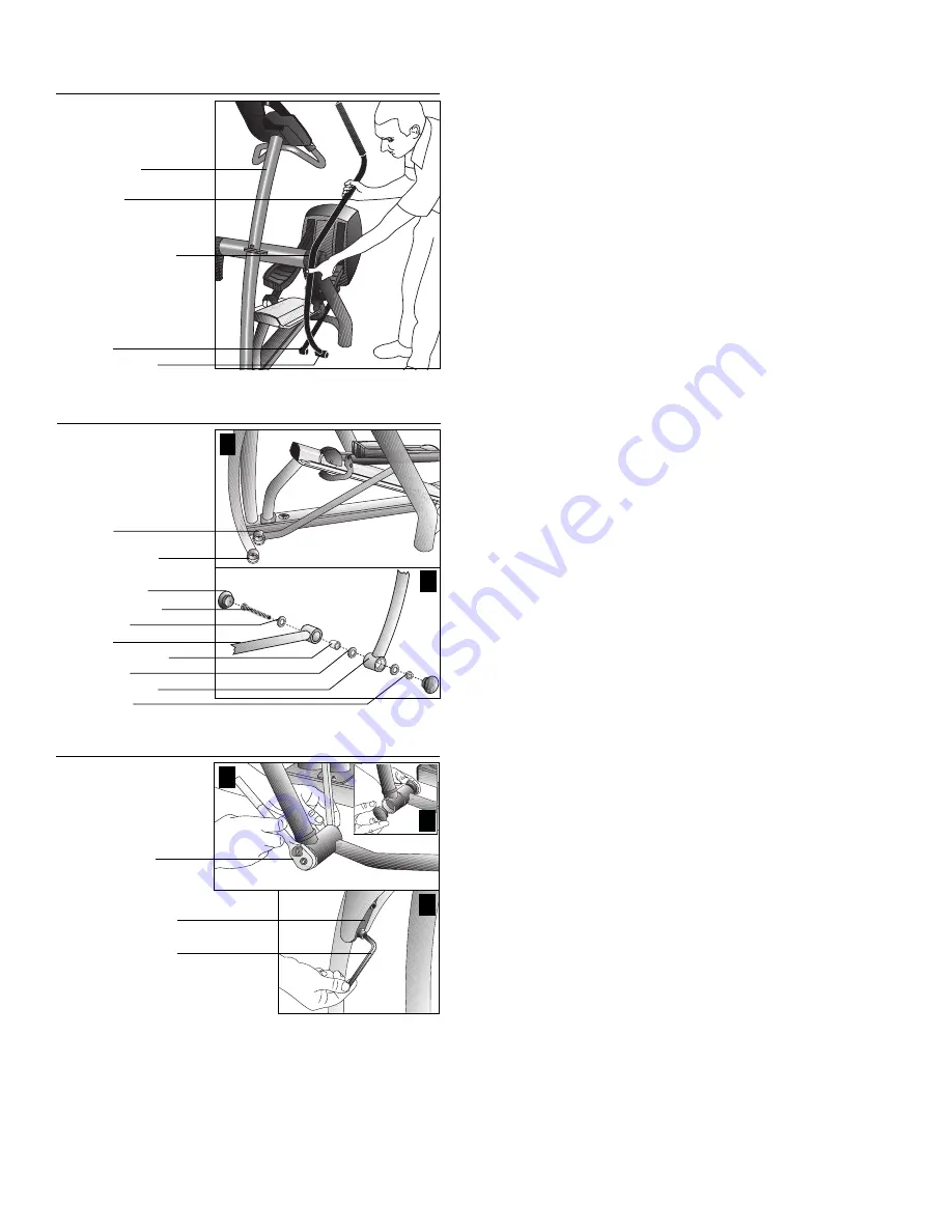
7. Attach the base of the handlebar to the foot pedal link arm.
Diagrams 2, 3, and 4.
a. Align the base of the handlebar with the foot pedal link arm.
Straighten the handlebar so that the link arm and handlebar
base fit together. Refer to Diagram 2.
b. Thread screw (E) with washer (F) through the link arm. Refer
to Diagram 3, #1 and #2.
Important: The head of the screw should be facing the EFX
®
. It
is inserted through the link arm first.
c. Place a spacer (G) and washer (F) on the end of the screw.
Insert the link arm onto the handlebar base and slide the screw
through it.
d. Slide a washer (F) and thread a locknut (H) on to the end of
the screw. Refer to Diagram 3, #2.
e. Wrench tighten using a
⁹⁄₁₆
-inch socket and open end wrench.
Refer to Diagram 4, #1.
Important: Once the fasteners are secured, use a
hex torque wrench to tighten the two linkage arm
screws to 200 in-lbs.
f. Position two plastic caps (J) over the ends of the handlebar
mounts. Press them into place. Refer to Diagram 4, #2.
8. Return to the handlebar bracket fasteners. Tighten all three
screws using a
¹⁄₄
-inch hex key. Diagram 4, #3.
Note: To complete the EFX
®
556i assembly, return to the
assembly steps in your owner’s manual.
1
2
Handlebar alignment.
Diagram 2
EFX
®
upright
Handlebar
Handlebar bracket
Link arm
Handlebar base
Handlebar and link arm
assembly.
Diagram 3
Link arm
Handlebar base
Steel bushing (G)
Washer (F)
Washer (F)
2-inch screw (E)
Plastic cap (J)
Link arm
Handlebar base
Locknut (H)
1
3
Finalize link arm and
handlebar bracket
assembly.
Diagram 4
Wrench tighten
link arm assembly.
¹⁄₄
-inch hex key (M)
Handlebar bracket
2


