


©2019 Precor Inc. | Converging Chest Press RSL 414 | Assembly Guide
9
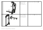
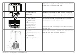
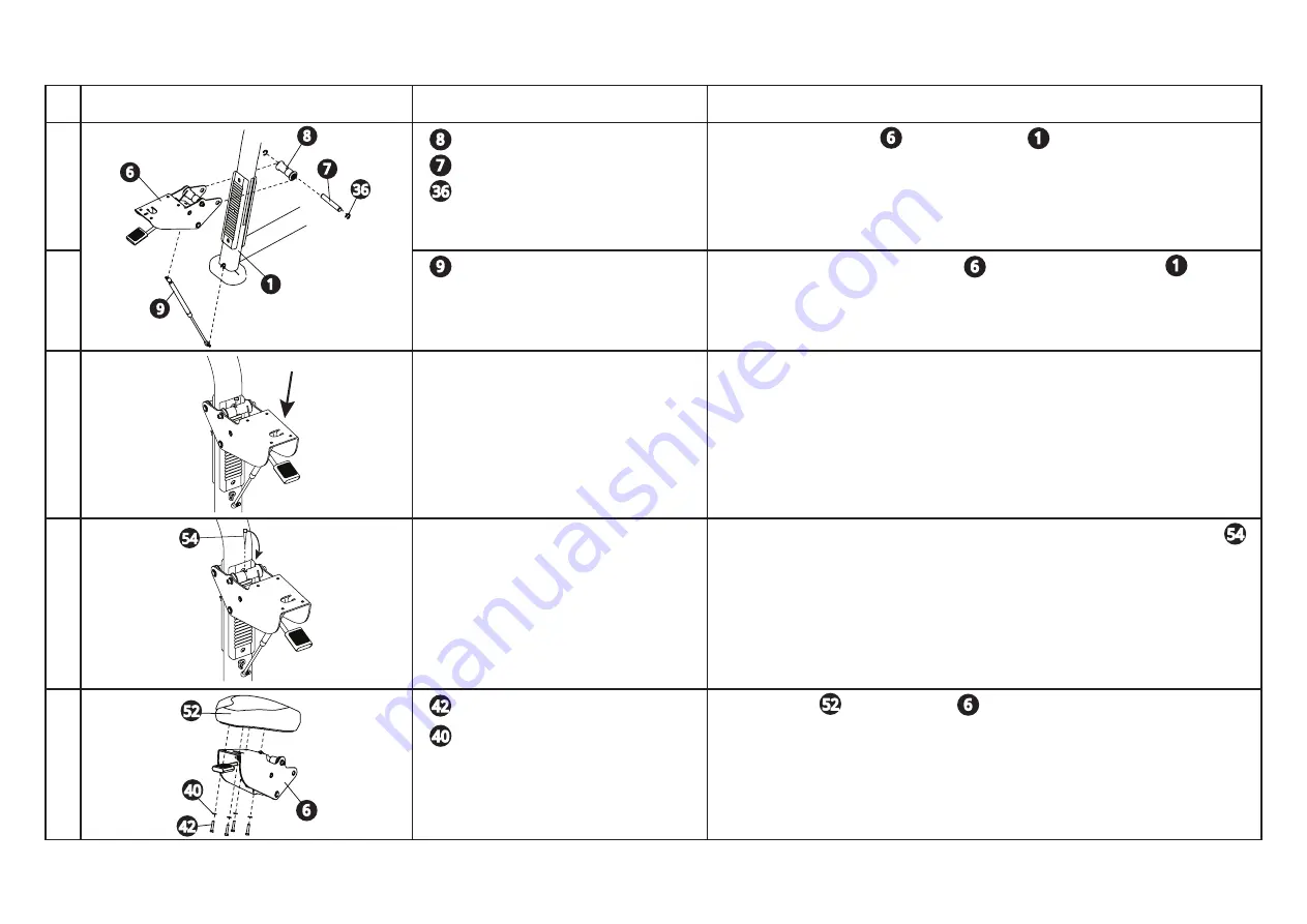
Seat Assembly
Image
Hardware
Instructions
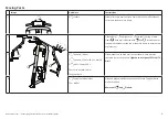
1
1 roller assembly
1 shaft
2 retaining rings, 3/4-inch
Tool: Pliers
Attach the seat assembly to the main frame . Place the roller assembly
between the seat assembly brackets and insert the shaft. Secure each side with
retaining rings.
2
1 gas spring
Snap gas spring into place under seat and at base of main frame . The larg-
er body of the gas spring attaches to the seat.
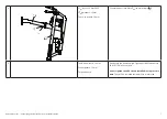
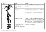
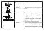
3
To adjust the roller clearance on the seat assembly, have your assistant apply
downward force on seat.
4
Tools: Two hex wrenches, 8 mm
Preinstalled on the front roller of the seat assembly is a roller adjustment tool .
Continue to apply force to the seat assembly and press the adjustment tool
down-
ward
to turn the roller. Turn until it just contacts the plastic ratchet plate and no
more than 180 degrees. Tighten the socket head screws on the sides of the front
roller (ensure the position of the roller tool does not change).
Remove tool.
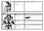
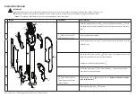
5
4 hex head screws 5/16 x 1½-inch
4 washers, 9 mm
Tool: Socket wrench, ½-inch with extension
Attach seat pad to seat assembly .
1
6
7
8
9
6
1
6
36
40
42
52
54
54
52
6
40
42
1
8
7
36
9
6


