© Precor Incorporated, Unauthorized Reproduction and Distribution Prohibited by Law
Page 48
Troubleshooting the 3 Phase AC Drive Motor System
Occasionally, there may be issues with the proper operation of the
drive system that do not generate error codes. This troubleshooting
procedure is intended for those times.
If there is an error code for the drive system (Error 20 through 29) in
the error log, go to the appropriate error code troubleshooting page
and follow the steps for that error.
If there are no errors in the log, yet the drive system appears to have
an issue (such as jittery motion) follow the steps below.
Note: When taking voltage readings of the AC drive motor, the readings
may not seem accurate because of the frequencies being used, however,
they are indicative of the presence of drive motor voltage and relative
frequency changes.
Procedure:
If the drive motor starts when you force the running belt to move and
once running the drive motor runs rough, skip to step 8. If the drive
motor will not start at all, continue with step 1.
If the drive motor does not start, the lower control module will only
apply voltage for a couple of seconds before it shuts down. Therefore
the voltage readings in the following step must be taken within the
first couple of seconds after the treadmill is instructed to start the
running belt. (A multi-meter with a hold feature is advisable in this
case)
1
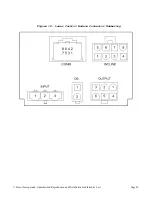
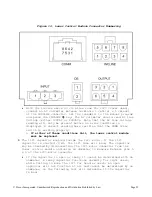
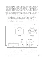
Connect an AC voltmeter between terminals 4 (red) & 5 (white) of the
OUTPUT connector on the lower control module.
See Figure Below
. Set
the treadmill’s on/off switch to the on position. Press the
QUICK
START
key. If the lower control module is supplying output, you will
momentarily read some value of AC voltage. Make a note of the value
and set the treadmill’s on/off switch to the off position.
2
Set the treadmill’s on/off switch to the off position and repeat the
procedure in step 1 between terminals 4 (red) & 6 (black) of the
OUTPUT connector on the power control module. Voltage should read
the same value as in step 1. Set the treadmill’s on/off switch to
the off position.
3
Set the treadmill’s on/off switch to the off position and repeat the
procedure in step 1 between terminals 5 (white) & 6 (black) of the
OUTPUT connector on the lower control module. Voltage should read
the same value as in step 1. Set the treadmill’s on/off switch to
the off position.
4
If one or more of the voltage readings in steps 1 through 3 are not
present, replace the lower control module. If the voltage readings
in steps 1 through 3 are present, continue with step 5.
Summary of Contents for TRM10/GEN06
Page 2: ......
Page 23: ...Precor Incorporated Unauthorized Reproduction and Distribution Prohibited by Law Page 21...
Page 93: ...Precor Incorporated Unauthorized Reproduction and Distribution Prohibited by Law Page 91...
Page 140: ...Precor Incorporated Unauthorized Reproduction and Distribution Prohibited by Law Page 138...
Page 141: ...Precor Incorporated Unauthorized Reproduction and Distribution Prohibited by Law Page 139...
Page 142: ...Precor Incorporated Unauthorized Reproduction and Distribution Prohibited by Law Page 140...
Page 143: ...Precor Incorporated Unauthorized Reproduction and Distribution Prohibited by Law Page 141...


