Installing the Console
25
4.
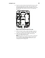
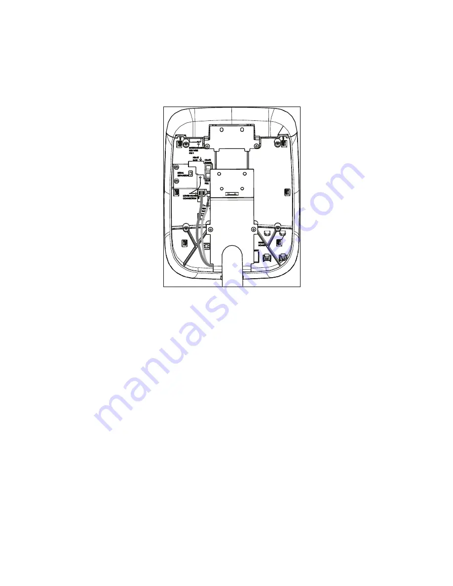
Route the twisted, red-and-black heart rate sensor cable
and the flat, gray base unit data cable to the left of the
mounting bracket and about three-quarters of the way up
the left side of the console, as shown in the following
illustration.
Figure 11: Routing the data and heart rate cables
5.
Attach the base unit data cable to the eight-conductor
modular jack labeled LOWER BOARD CONNECTION.
6.
Attach the heart rate sensor cable to the four-pin
connector labeled HEART RATE.
Note:
The cables on the connector and the circuit board
can fit together in only one way. There may also be a
10-pin connector labeled HEART RATE, but it is not
compatible with the equipment.
Summary of Contents for UBK 815
Page 1: ...Assembling and Maintaining the UBK 815 Upright Exercise Bike ...
Page 2: ......
Page 3: ...Assembling and Maintaining the UBK 815 Upright Exercise Bike ...
Page 40: ...38 Assembling and Maintaining the UBK 815 Upright Exercise Bike Notes ...
Page 41: ...Notes 39 Notes ...
Page 42: ...40 Assembling and Maintaining the UBK 815 Upright Exercise Bike Notes ...
Page 43: ......
Page 45: ...Product Owner s Manual UBK 815 RBK 815 ...
Page 46: ......
Page 47: ...Product Owner s Manual RBK 815 UBK 815 ...
Page 56: ...10 Product Owner s Manual ...
Page 88: ...42 Product Owner s Manual Notes ...
Page 89: ...Notes 43 Notes ...
Page 90: ...44 Product Owner s Manual Notes ...
Page 91: ......

