background image

Page 6

For technical questions, please call 1-888-866-5797.

ITEM 69733 


SAFETY

Op
ERA
TION

M

AINTENANCE

SETU
p

Set Up

Read the ENTIRE IMpORTANT SAFETY INFORMATION section at the beginning of this manual 

including all text under subheadings therein before set up or use of this product.

TO pREVENT SERIOUS INJURY: 

Operate only with proper spark arrestor installed.
Operation of this equipment may create sparks that can start fires around dry vegetation. 

A spark arrestor may be required. 

The operator should contact local fire agencies for laws or 

regulations relating to fire prevention requirements.

At high altitudes, the engine’s carburetor, governor (if so equipped), and any other parts that control 

the fuel-air ratio will need to be adjusted by a qualified mechanic to allow efficient high-altitude 

use and to prevent damage to the engine and any other devices used with this product.
The emission control system for this Engine is warranted for standards set by the U.S. Environmental 

Protection Agency.  For warranty information, refer to the last pages of this manual.

WARNING!  DO NOT INSTALL THIS ENGINE ON A VEHICLE. 

NOT FOR HIGHWAY USE.  FOLLOW ALL AppLICABLE LAWS FOR INSTALLATION AND USE.

Mounting

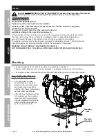
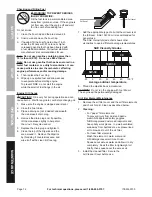
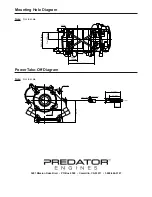
1.  The engine needs to be mounted using all four mounting holes on its base.   

These mounting holes are not in an exact rectangle - see diagram on back cover of this manual.

2.  This engine includes a Mounting Plate and 4 Mounting Plate Bolts to assist in mounting the engine.

Note: The Mounting plate only 

attaches to the engine one way.

3.  A mounting plate can also 

be fabricated, but it needs to 

attach to all four mounting holes 

and must be strong enough to 

withstand the forces created during 

operation after repeated use.

4.  After attaching the Mounting Plate 

to the engine, use the mounting 

plate to mount the engine away 

from the equipment operator and 

where it will not cause damage 

by its moving or hot parts.

Mounting 

plate

Mounting 

plate Bolt

Summary of Contents for 79cc

Page 1: ...onth and year of purchase if product has no number Keep this manual and the receipt in a safe and dry place for future reference When unpacking make sure that the product is intact and undamaged If an...

Page 2: ...M 3600 RPM Compression Ratio 8 5 1 Bore x Stroke 52 mm x 37 mm 2 0 IN x 1 5 IN Fuel Type 87 octane stabilizer treated unleaded gasoline Engine Oil Capacity 0 37 Quart 0 35 L Fuel Tank Capacity 0 53 Ga...

Page 3: ...e Injury Wear ANSI approved safety goggles with side shields Read the manual before set up and or use WARNING marking concerning Risk of Hearing Loss Wear hearing protection Symbol Property or Stateme...

Page 4: ...ngine 8 Secure the Engine on transport vehicles to prevent the tool from rolling slipping and tilting 9 Industrial applications must follow OSHA requirements 10 Do not leave the equipment unattended w...

Page 5: ...se for which it is not intended Service Precautions 1 Before service maintenance or cleaning a Turn the engine switch to its OFF position b Allow the engine to completely cool c Then remove the spark...

Page 6: ...this product The emission control system for this Engine is warranted for standards set by the U S Environmental Protection Agency For warranty information refer to the last pages of this manual WARNI...

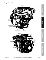
Page 7: ...l questions please call 1 888 866 5797 ITEM 69733 Safety Operation Maintenance Setup Engine Controls Starter Handle Oil Drain Plug Serial Number Location Air Filter Muffler Choke Fuel Cap Throttle Dip...

Page 8: ...in the Service section shows other viscosities to use in different average temperatures 6 Thread the dipstick back in clockwise NOTICE Do not run the engine with too little oil The engine will be perm...

Page 9: ...Throttle when the tool is so equipped 3 Turn the Engine Switch on 4 Grip the Starter Handle of the Engine loosely and pull it slowly several times to allow the gasoline to flow into the Engine s carbu...

Page 10: ...ast about 3 hours of use During this period Do not apply a heavy load to the equipment Do not operate the engine at its maximum speed c The maintenance break in period will last about 20 hours of use...

Page 11: ...stead Cleaning Maintenance and Lubrication Schedule Note This maintenance schedule is intended solely as a general guide If performance decreases or if equipment operates unusually check systems immed...

Page 12: ...e a drain pan not included underneath the crankcase s drain plug 4 Remove the drain plug and if possible tilt the crankcase slightly to help drain the oil out Recycle used oil 5 Replace the drain plug...

Page 13: ...adually enter the Engine and cause rust damage Apply a thin coat of rust preventive oil to all metal parts 2 FUEL To protect the fuel tank during storage fill the tank with gasoline that has been trea...

Page 14: ...chamber with screwdriver handle 8 Turn Choke to RUN position Remove spark plug and pull the start handle several times to air out the chamber Reinstall spark plug and set Choke to CHOKE position 9 Re...

Page 15: ...ne Do not use gasoline with more than 10 ethanol E15 E20 E85 etc 3 Test replace fuel tank cap 4 Have qualified technician service magneto 5 Secure spark plug cap Engine stops when under heavy load 1 D...

Page 16: ...explain the emission control system warranty on your 2014 2015 Small Off Road Engine herein engine Within the United States new off road spark ignition engines certified for model year 2014 2015 must...

Page 17: ...lterations by changing adding to or removing parts from the engine 5 Service and Maintenance Component parts which are not scheduled for replacement as required maintenance or are scheduled only for r...

Page 18: ...te Subassembly Lifter Stopper 1 45 Bolt Valve Adjusting 2 Part Description Qty 46 Rocker Valve 2 47 Nut Valve Adjusting 2 48 Nut Valve Lock 2 49 Starter Assy Recoil 1 50 Bolt 3 51 Shroud 1 52 Bolt 4 5...

Page 19: ...13 16 15 14 20 19 18 21 25 88 87 87 86 83 82 85 84 64 64 63 59 59 61 60 62 55 54 53 56 51 52 52 52 52 57 58 49 50 50 50 76 77 78 79 80 80 81 38 40 42 43 44 45 46 47 42 43 45 46 47 48 39 40 41 41 48 3...

Page 20: ...ole Diagram Note Not to scale 1 in 25 5mm 2 42 in 61 5mm 4 02 in 102mm 1 44 in 36 5mm Power Take Off Diagram Note Not to scale 0 98 in 25mm 1 79 in 45 5mm 2 37 in 60 1mm 5 16 24UNF 0 1875 in 4 76mm 0...

Reviews: