16
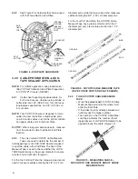
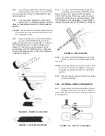
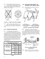
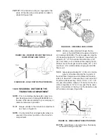
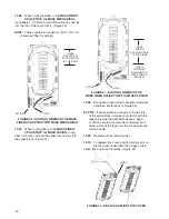
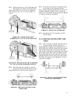
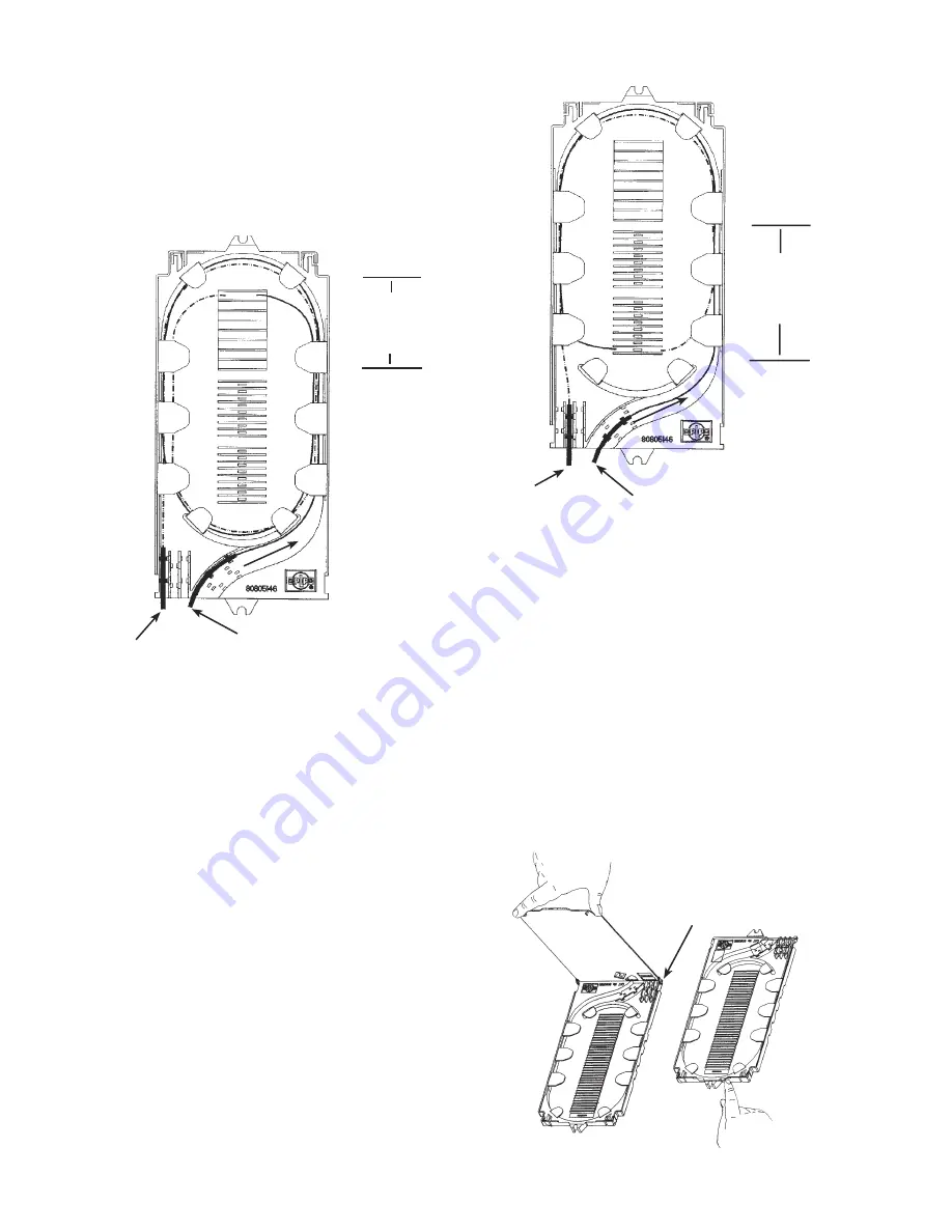
FIGURE 41 - ROUTING FIBERS IN THE
MASS FIBER SPLICE TRAY FOR MASS FUSION
13.08
Splice fibers according to accepted company
practices. (Refer back to Figure 38)
PLP TIP:
If splice protectors loosely fit in the slots
of the splice block, wrap each protector with felt
tape to provide the desired fit
or
use a bead
of silicone caulk to secure the connectors and
place a strip of felt tape over the connectors and
silicone caulk.
13.09
Replace all tray retaining tabs.
13.10
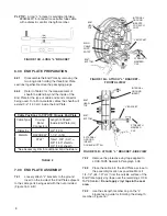
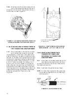
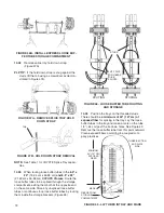
To replace tray cover, position pivotal arm on
plastic cover underneath the hinges on the
splice tray and snap into place. (Figure 42)
FIGURE 42 - REPLACE SPLICE TRAY COVER
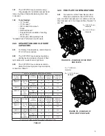
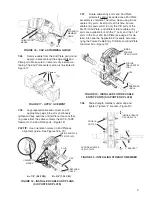
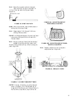
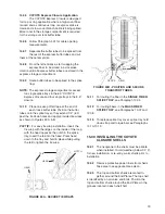
13.06
When routing the fiber in the
MASS FIBER
SPLICE TRAY for MASS MECHANICAL
,
route fibers 1-1/2 times around the splice tray and lay
into the top of the splice block. (Figure 40)
NOTE:
There should be a minimum of 50" (127 cm)
of exposed fiber for splicing.
FIGURE 40 - ROUTING FIBERS IN THE MASS
FIBER SPLICE TRAY FOR MASS MECHANICAL
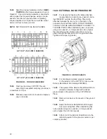
13.07
When routing fibers in the
MASS FIBER
SPLICE TRAY for MASS FUSION
, route
fiber 1-3/4 times around the splice tray and lay into
the splice block. (Figure 41)
HINGE
MASS
MECHANICAL
SPLICE BLOCK–
8 POSITIONS
FIELD
OFFICE
FIELD
OFFICE
MASS
FUSION
SPLICE BLOCKS–
16 POSITIONS
(USE 12
POSITIONS
MAXIMUM FOR
MASS FUSION
SPLICES)
Summary of Contents for COYOTE 80805112
Page 23: ...23...

