18
ROUTING STORING
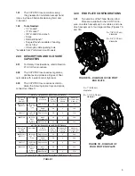
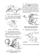
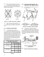
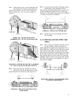
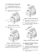
FIGURE 48 - LOOSE BUFFER TUBE ROUTING
AND STORAGE
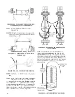
14.04
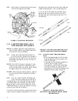
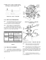
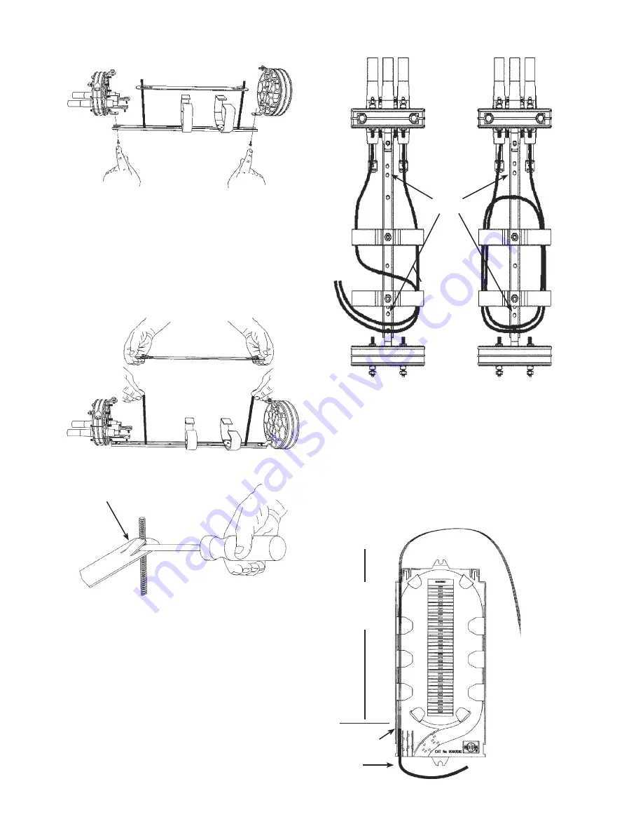
Position the trays on the threaded studs.
There should be
a minimum of 50" (127 cm) of
exposed fiber
for splicing in the tray. Lay the loose
buffer tubes in the tray and make a mark on the tube
1/4" (.64 cm) past the tie down holes. See Figure 49.
Remove the loose buffer tube from this point outward.
Clean exposed fibers according to accepted com-
pany practices.
FIGURE 49 - LAY TUBES IN TRAY AND MARK
STUDS
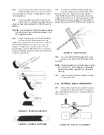
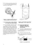
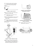
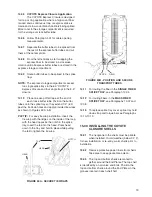
FIGURE 46B - INSTALL EXPRESS LOOSE BUF-
FER TUBE STORAGE COMPARTMENT
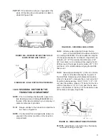
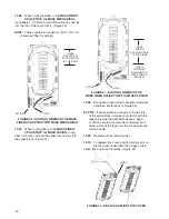
14.02
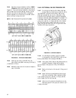
Remove splice tray hold down strap.
(Figure 47A)
PLP TIP:
If the hold down strap is snug against the
studs, lift the tab using a screwdriver as demon-
strated in Figure 47B.
FIGURE 47A - REMOVE SPLICE TRAY HOLD
DOWN STRAP
FIGURE 47B - HOLD DOWN STRAP REMOVAL
NOTE:
See Table 1 for COYOTE Splice Tray capaci-
ties.
14.03
When routing loose buffer tubes in the
6.0" x
22"
(15.24 cm x 55.88 cm)
and 8.5" x 22"
(21.59 cm x 55.88 cm)
COYOTE Closure
. Route the
loose buffer tubes to be spliced through the storage
compartment, exiting them both at the opposite end
on the same side. Store any unspliced loose buffer
tubes or continuous loop loose buffer tubes by routing
them inside the storage brackets. (Figure 48)
MARK
➔
THREE-SECTION
END PLATE
SIDE
FIBERS FROM
STORAGE
COMPARTMENT
MINIMUM
50" (127 CM)
EXPOSED
FIBER
TAB
EXIT POINT
FOR FIBERS
TO BE
SPLICED
Summary of Contents for COYOTE 80805112
Page 23: ...23...


