4
Assembly Instructions, POWER RAIL
TM
‒ Two-Tier Tilt Kit
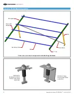
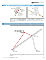
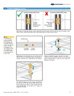
2 Measure and Mark the “L” Foot and the Leg Attachment Points on the Strongbacks
CAUTION
Span dimensions
are a design spec
-
ification. Consult
the design manual
to match these
dimensions to site
conditions. It’s
important to use
the unique span
dimension specific
to the install. Fail
-
ure to do so could
lead to excessive
deflection and/or
premature system
failure.
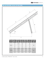
To ensure consistency and structural integrity, the
attachment points of the “L” Feet and Legs must be in
accordance with the above diagram and the “Spacing
Calculations” on page 3. Measure and mark each
Strongback to establish attachment points for the “L”
Foot and Leg.
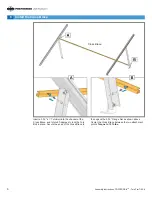
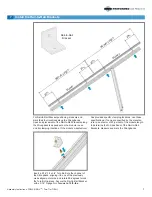
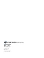
Insert a 1/2”-13 x 1-1/2” Carriage Bolt into channel of
Strongback and slide it down to the previously made
alignment mark. Install the Leg and secure with a 1/2”
Flat Washer, Lock Washer and Nut. Tool tighten for
now allowing the Leg to pivot/rotate as needed and
align to the “L” Foot.
3 Attach the Leg to the Strongback
Leg
Alignment
Mark
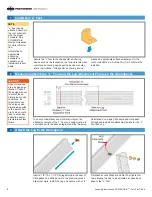
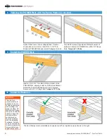
1 Install the “L” Feet
Secure the “L” foot to the site-specific anchoring
device such as the foundation, roof structural member,
or surface anchoring device per the device manufac
-
turers’ instructions. “Site specific anchoring device”
NOTE
“L” Feet can be
attached directly to
the roof substrate
with the proper
hardware. See
POWER RAIL
Design Guidelines
for more informa
-
tion.
Information on
appropriate
anchoring
hardware is
available on an
individual product
basis.
means an appropriate surface attachment for the
roof or substrate in which the Two-Tier Tilt Kit will be
installed.


