Assembly Instructions, Power Rail P6 (Version 2, Rev A)
5
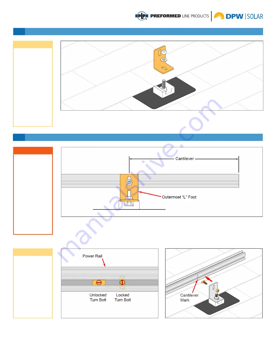
2 Attach Power Rail to “L” Feet
Insert 5/16” x 3/4” Turn Bolt into Power Rail and
rotate 90-degrees, locking Turn Bolt in place. On the
outermost “L” Feet align center of the “L” Foot with the
The Power Rail overhangs beyond the outermost
“L” Foot. This overhang is referred to as “cantilever”,
or abbreviated as “C’ver”. The distance between
adjacent “L” Feet is referred to as “span”. The length
of both the cantilever and the span are dependent on
cantilever mark on the Power Rail. Secure Power Rail
to “L” Foot with 5/16” Flange Nut.
Torque to 14-16
ft.-lbs.
1 Install the “L” Feet
Secure “L” foot to appropriate anchoring device per
the manufacturers instructions. Above is shown using
the Power Rail PV Flash and attaching hardware.
Position “L” foot on compression block and secure
with 5/16” Hex Nut and Flat Washer.
Torque to 14-16
ft.-lbs.
CAUTION
NOTE
NOTE
Cantilever and
span dimensions
are a design spec-
ification. Consult
the design manual
to match these
dimensions to site
conditions. It’s im-
portant to use the
unique cantilever
and span dimen-
sion specific to the
install. Failure to do
so could lead to ex-
cessive deflection
and/or premature
system failure.
L feet can be
attached directly to
the roof substrate
with the proper
hardware. See
Power Rail Design
Guidelines for more
information.
Information on
appropriate
anchoring
hardware is
available on an
individual product
basis.
Turn bolts must
be locked into
the channel by
rotating clockwise
90-degrees. Use
the indicator slot on
the threaded end
to identify whether
or not the bolt has
been locked.
several factors, unique to each installation and are
determined by the system design.
Measure and mark the cantilever dimension supplied
by the design manual onto the Power Rail.


