4
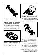
FIGURE 7 - END PLATE SHOWING THE
DESIGNATED DRILL MARKS
5.02
To enable bonding/strain relief brackets to be
properly applied, the cable holes must be
drilled at the designated drill marks highlighted in
yellow.
5.03
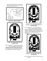
To position End Plate in the cutter:
— Rotate End Plate and slide bearing block
along the guides until the drill is positioned over
designated drill marks.
— Then, tighten the clamp screw and
thumbscrew on the bearing block. (Figure 8).
FIGURE 8 - BLADE POSITION
CAUTION:
A small nylon pellet backs up the
thumbscrews in the bearing block. Using
cutter with pellet missing could cause damage
to the guide rails.
To prevent damage, remove the thumbscrews and
insert a small piece of cable sheath. Additional nylon
pellets are available from PLP®.
5.04
Mount a 3/8" drill, drill blade adapter, and one
1/2" deep well socket to the upper end of the bearing
block shaft.
PLP TIP:
A special drill motor is available from
Preformed Line Products. No matter what type
of electric drill you use, be sure to press down on
the body of the drill so that pressure is not
exerted sideways on the shaft. This will result in
a much longer life of the bearing blocks. Drill
through the End Plate slowly.
5.05
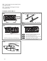
When using blades E-DD in the drill adapter,
cut through the black plastic of the End Plate
until foam is just visible in the outer ring. (Figure 9)
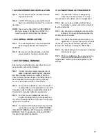
Use a screwdriver to pop out the plastic disk (not
necessary for A-D drill bits). (Figure 10)
FIGURE 9 - CUTTING THROUGH PLASTIC SHELL
FIGURE 10 - REMOVING PLASTIC DISK
5.06
Drill through the End Plate until the shaft
bottoms out on the stop collar. When the
drill has bottomed out, stop the drill.
CAUTION:
Never bring the blade back up through
End Plate while it is still turning. This could
result in an oversized hole. Do not exert
sideways pressure on drill shaft, it may cause
damage to the bearing block.
5.07
If additional holes are needed, repeat
preceding steps 5.03 - 5.06. (Figure 11)

