5
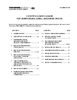
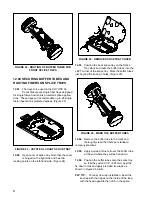
FIGURE 11 - END PLATE WITH HOLES DRILLED
5.08
Remove the End Plate from the cutter and
disassemble End Plates by removing both bolts.
6.00 END PLATE PREPARATION -
LOCK-TAPE SEALANT
APPLICATION
6.01
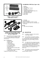
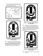
Remove sharp edges on plastic and foam in
area of opening with emery cloth (provided).
(Figure 12)
SCUFF LIGHTLY.
DO NOT REMOVE TOO MUCH MATERIAL
FIGURE 12 - SCUFFING CABLE OPENINGS
PLP TIP:
This simple operation will help prevent
catching the LOCK-TAPE Sealant when drawing
the End Plates together. ONLY USE EMERY
CLOTH PROVIDED FOR THIS PROCEDURE.
6.02
Apply a thin coat of C-Cement to each inside
surface of the End Plate sections.
6.03
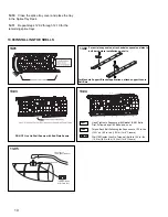
When the C-Cement becomes tacky, remove
protective backing from a strip of LOCK-
TAPE Sealant.
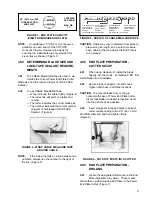
PLP TIP:
Use removed backing from a LOCK-
TAPE Sealant strip to dry and remove excess C-
Cement applied to End Plate. (Figure 13)
FIGURE 13 - C-CEMENT ON END PLATE
6.04
Without stretching, apply LOCK-TAPE
Sealant over prepared surface of the End
Plates, following the contour of the cable holes.
Allow approximately 3/4" (19.05 mm) of LOCK-TAPE
Sealant to extend beyond each end of the End Plate.
This will serve as a tighting indicator during the End
Plate assembly.
6.05
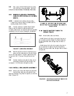
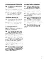
Square cut the tape away from the bolt
holes. (The area just beyond the metal
insert.) (Figure 14)
FIGURE 14 - SQUARE CUT BOLT HOLES
7.00
CABLE PREPARATION - APPLYING
LOCK-TAPE SEALANT TO
CABLES FOR FIELD-DRILLED END
PLATES
7.01
Measure and mark the cables at 80" (2.03 m)
for the opening of the sheath.
7.02
Remove the cable sheath to open the
appropriate amount of cable. Remove any
other coverings to expose the buffer tubes in the
center of the cable.
7.03
The cable must now be marked for the
installation of the LOCK-TAPE Sealant.

