7
8.08
Trim excess LOCK-TAPE Sealant to within
1/8" (3.18 mm) of the End Plate. DO NOT
STRETCH TAPE DURING TRIMMING PROCESS.
9.00
BONDING AND/OR GROUNDING
CABLES WITH METALLIC COMPO-
NENTS
NOTE:
Installation of bonding and grounding
components may be easier if installed prior to
placing cables into End Plate.
9.01
If cable contains a metallic shield, install
shield connector and/or bonding assembly per
company instructions. A shield connector is available
separately from PLP under Catalog No. 80803989.
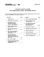
FIGURE 19 -BONDING ASSEMBLY
9.02
After the bond connector is installed on the
cable and the cable placed in the End Plate
next to the appropriate “L” bracket, attach the bond
connector to the “L” bracket through the slot pro-
vided.
9.03
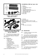
If cable contains a strength member, insert
the strength member into the retainer clip
and tighten. Cut off excess strength member.
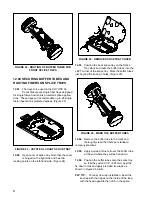
10.00 INSTALL ORGANIZER ASSEMBLY
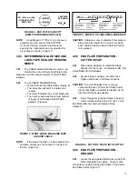
10.01
Remove the torque bar attachment bolt from
the End Plate and secure the Buffer Tube
Storage and Splice Tray Rack Torque Bar to the End
Plate. (Figure 20)
FIGURE 20 - BUFFER TUBE STORAGE AND
SPLICE TRAY RACK ASSEMBLY SECURED TO
END PLATES
11.00 ROUTE BUFFER TUBES TO
SPLICE TRAYS
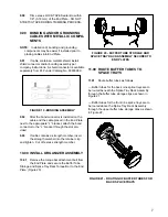
11.01
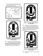
Route buffer tubes as follows:
— Buffer tubes for the back nine splice trays are to
be routed beneath the Splice Tray Rack Assembly
through the buffer tube storage clips as shown in
Figure 21.
— Buffer tubes for the front nine splice trays are to
be routed above the Splice Tray Rack Assembly
through the upper buffer tube storage clips as shown
in Figure 22.
FIGURE 21 - ROUTING OF BUFFER TUBES FOR
BACK SPLICE TRAYS

