8
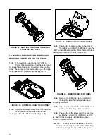
FIGURE 22 - ROUTING OF BUFFER TUBES FOR
FRONT SPLICE TRAYS
12.00 SECURING BUFFER TUBES AND
ROUTING FIBERS ON SPLICE TRAYS
12.01
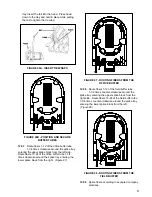
The trays to be used in the COYOTE Hi-
Count Closure are single fiber trays designed
for single fusion heat shrink protected splice applica-
tions. These trays can accommodate up to 24 single
fusion heat shrink protected splices. (Figure 23)
FIGURE 23 - COYOTE HI-COUNT SPLICE TRAY
12.02
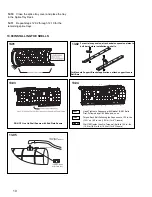
Open cover of splice tray. Note that the cover
is hinged on the right side and has two
locking points on the left-hand side. (Figure 24)
FIGURE 24 - REMOVE SPLICE TRAY COVER
12.03
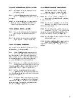
Position the back splice tray on the Splice
Tray Rack and route the buffer tubes into the
LEFT corner of the splice tray. Mark the buffer tubes
just beyond the tie down holes. (Figure 25)
FIGURE 25 - MARK THE BUFFER TUBES
12.04
Remove the buffer tube to the mark and
thoroughly clean the fibers per standard
company practices.
12.05
Apply a wrap of blue felt over the buffer tube
at the end where they will be tied down.
12.06
Position the buffer tubes onto the splice tray
so that they extend 1/4" (6.35 mm) past the
tie down holes and apply provided tie wraps as
shown in Figure 26 A & B.
PLP TIP:
For easy tie wrap installation, insert the
tie wrap with the ridges on the inside of the loop,
with the head opposite the notch in the splice

