9
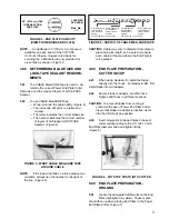
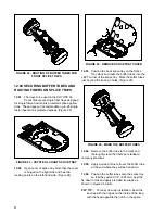
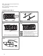
FIGURE 27 - ROUTING FIBERS FROM THE
OFFICE BUFFER
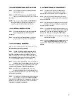
12.08
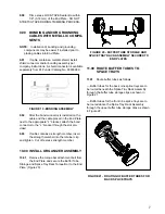
Route fibers 1-12 of the field buffer tube
1-1/2 times counter-clockwise around the
splice tray entering the upper splice block from the
right side. Route fibers 13-24 of the field buffer tube
1-3/4 times counter-clockwise around the splice tray
entering the lower splice block from the left.
(Figure 28)
FIGURE 28 - ROUTING FIBERS FROM THE
FIELD BUFFER
12.09
Splice fibers according to accepted company
practices.
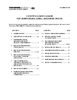
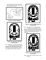
tray. Insert the tail into the head. Press head
down to the tray and hold in place while pulling
the tail to tighten the tie wrap.
FIGURE 26A - INSERT TIE WRAPS
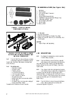
FIGURE 26B - POSITION AND SECURE
BUFFER TUBES
12.07
Route fibers 1-12 of the office buffer tube
1-1/4 times clockwise around the splice tray
entering the upper splice block from the left side.
Route fibers 13-24 of the office buffer tube 1-3/4
times clockwise around the splice tray entering the
lower splice block from the right. (Figure 27)

