Don't Be Afraid Of The Dark...
WARRANTY AND DISCLAIMER: We warrant Akron Brass products for a period of five (5) years after purchase against defects in materials or workmanship. Akron Brass will repair or replace product
which fails to satisfy this warranty. Repair or replacement shall be at the discretion of Akron Brass. Products must be promptly returned to Akron Brass for warranty service.
We will not be responsible for: wear and tear; any improper installation, use, maintenance or storage; negligence of the owner or user; repair or modification after delivery; damage; failure to follow our
instructions or recommendations; or anything else beyond our control. WE MAKE NO WARRANTIES, EXPRESS OR IMPLIED, OTHER THAN THOS INCLUDED IN THIS WARRANTY STATEMENT, AND
WE DISCLAIM ANY IMPLIED WARRANTY OF MERCHANTABILITY OR FITNESS FOR ANY PARTICULAR PURPOSE. Further, we will not be responsible for any consequential, incidental or indirect
damage (included, but not limited to, any loss or profits) from any cause whatsoever. No person has authority to change this warranty.
PHONE: 330.264.5678 or 800.228.1161 FAX:330.264.2944 or 800.531.7335 www.akronbrass.com
A Premier Farnell Company
MOUNTING INSTRUCTIONS FOR
ELECTRIC REWIND CORD REEL
1-
Unpack the shipping box. Inside you will find an Extenda-Lite
Electric Rewind Cord Reel
that is totally prewired.
2-
Inspect the box and all items inside for damage. Report any damage to the delivering carrier immediately. If there is any
damage, save the box and all packing materials.
3-
Before doing any wiring make certain the power cord to the cord reel is completely disconnected from its
junction box or power supply. Have a Licensed Electrician do all wiring.
4-
If the hub is going to remain on the frame during installation please skip to line13.
5-
Remove the six screws that attaches the upper guard to the frame and lower guard and set upper guard aside.
6-
Remove the four screws that attaches the lower guard to the frame and set lower guard aside.
7-
Loosen the four bolts that attach the motor to the frame.
8-
Adjust motor to put slack in the chain and remove chain from small sprocket on motor.
9-
Remove the 4 bolts that secures the isolator mounts on either side of the disks.
10- Remove hub/disk assembly and set aside.
11- If the motor is going to remain on the frame during installation please skip to line 13.
12- Remove the four bolts that attach the motor to the frame and set motor aside.
13- Properly orientate frame (Remember motor can be mounted on left or right side by simply rotating hub/disk assembly
before reassembly.
14- Holes have been predrilled along the base of the frame for mounting purposes. Mount frame level.
15- After frame is mounted attach motor back to frame. (If removed in step 10)
16- Attach hub/disk assembly to frame (If removed in step 3) and reattach chain guards.
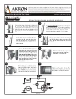
17- Attach cord to the 1' pigtail coming out of the hub - Black to Black, White to White, Green to Green and
Red to Red (if 4 wire)
See other side for detailed instructions. Please note 4 wire is not available on
the ERWC-16-6.
18- Run wire from 12 volt power source to relay to circuit breaker to switch to motor.
(Per the manufacturer's
instructions the solenoid should be mounted as close as possible to the battery as possible.)
19- Run wire from AC power source to gang box on side of reel. Depending on how reel was specified the gang box will
either be direct wired to reel or there will be a 4' pigtail between gang box and frame.
20- Insert wire from power source through side of gang box and attach to the cooresponding slot on terminal block -
Black to Black, White to White, Green to Green and Red to Red (if 4 wire).
Please note 4 wire is not available on the
ERWC-16-6.
Page 33


