background image


Page | 4 


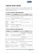
Subject 

Information 

Location 

environment 

WinCE 

development 

and 

compilation environment 

User  Manual->4.4.1  Installation  of 
IDE 

4.4.2 Extract BSP and project files to 
IDE 

Recompile 
system image 

Recompile Linux system image 

User 

Manual->3.4.2 

System 

Compilation 

Recompile WinCE system image 

User  Manual->4.4.3  Sysgen  &  BSP 
Compilation 

Software 
development 

Introduction  to  Linux  drivers 
and related driver development 
processes 

User 

Manual->3.5 

Driver 

Introduction 

3.6 Driver Development 

Introduction  to  WinCE  drivers 
and related driver development 
processes 

User  Manual  ->  4.4.4  Driver 
Introduction 

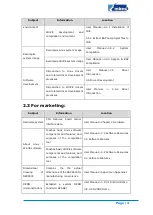
2.3


For marketing: 

Subject 

Information 

Location 

Hardware system 

CPU  features,  board  carrier 
interface data 

User Manual->Chapter 2 Hardware 

About  Linux  / 
WinCE software 

Teaches  basic  Linux  software 
components and features, and 
purposes  of  the  compilation 
tool 

User Manual->3.2 Software Resources 

3.3 Software Features 

Teaches basic WinCE software 
components and features, and 
purposes  of  the  compilation 
tool 

User Manual->4.2 Software Resources 

4.3 Software Features 

Dimensional 
drawing 

of 

SBC8530 

Contains  the  the  actual 
dimensions of the SBC8530 for 
manufacturing convenience 

User Manual->Appendix->Appendix I 

DEMO 
(demonstration) 

Establish  a  system  DEMO 
(Android, DVSDK) 

User Manual->3.8.3.1 Android Demo 

3.8.3.2 DVSDK Demo 

Summary of Contents for Embest SBC8530

Page 1: ...SBC8530 1GHz ARM Cortex Based Single Board Computer Quick Start Guide Version 2 1 22nd Jan 2014...

Page 2: ...Technology has the copyright of this document and reserves all rights Any part of the document should not be modified distributed or duplicated in any approach and form without prior written permissi...

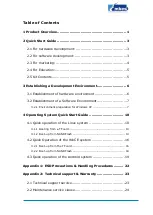
Page 3: ...t 7 3 2 1 Environment preparation for Windows XP 7 4 Operating System Quick Start Guide 10 4 1 Quick operation of the Linux system 10 4 1 1 Booting from a TF card 10 4 1 2 Boot up from NAND Flash 14 4...

Page 4: ...2 3 Basic guidelines for protection and maintenance of LCDs 25 2 4 Value Added Services 26...

Page 5: ...f the default configuration of both software and hardware of the evaluation board Quick establishment of a development environment for the evaluation board Quick start user guide for the Linux WinCE A...

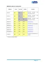
Page 6: ...ment board CAM8000 A YES NO NO CD ROM provided with Development board CAM8000 D YES YES YES Download here CAM8100 U YES YES YES CD ROM Provided Separately CDMA8000 U YES YES YES Download here GPS8000...

Page 7: ...imensions of the SBC8530 for manufacturing convenience User Manual Appendix Appendix I 2 2 For software development Subject Information Location Establishing a testing environment To connect with exte...

Page 8: ...sses User Manual 4 4 4 Driver Introduction 2 3 For marketing Subject Information Location Hardware system CPU features board carrier interface data User Manual Chapter 2 Hardware About Linux WinCE sof...

Page 9: ...o DB9 5V 2A power adapter USB main data line type A male to type mini B male USB slave data line type A female to type mini A male Crossover Ethernet cable HDMI to DVI D cable S Video cable WiFi anten...

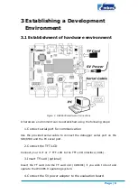
Page 10: ...serial port for communication Use the provided serial cable to connect the debugger serial port on the SBC8530 and the PC serial port 2 Connect the TFT LCD Connect your 4 3 or 7 TFT LCD to the TFT LCD...

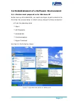
Page 11: ...boot up of the SBC8530 you need to configure HyperTerminal on the PC follow the process below in order to setup a Hyper Terminal connection 1 From the desktop click Start All Programs Accessories Comm...

Page 12: ...a new HyperTerminal connection Figure 3 Setting HyperTerminal Connection Name Icon 3 Select the specific serial port from the list as per your computers COM port configuration Figure 4 HyperTerminal...

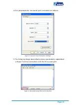
Page 13: ...l port connection as follows Figure 5 HyperTerminal Connection Settings 5 The following image shows that we have successfully established a Hyper Terminal connection with the PC s serial port Figure 6...

Page 14: ...card provided with the SBC8530 is supplied preinstalled with a WinCE6 0 operating system The steps below show the process of booting up from a TF card 1 Format the MMC SD card We recommend the HP USB...

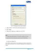
Page 15: ...complete then click OK Note HP USB Disk Storage Format Tool will erase the partitions of TF card Use other format tool may cause the failure of the TF card booting 2 Load kernel image file Copy all fi...

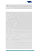
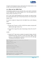
Page 16: ...ting OS Bootloader U Boot 2010 06 rc1 svn Mar 04 2011 10 18 34 OMAP34xx 35xx GP ES2 0 CPU OPP2 L3 165MHz OMAP3 SBC8530 board LPDDR NAND I2C ready DRAM 512 MiB NAND 512 MiB Warning bad CRC or NAND usin...

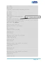
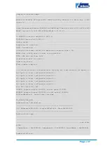
Page 17: ...unting root file system mount mounting dev root on failed Invalid argument mount mounting dev root on failed Invalid argument root mount mounting rootfs on failed No such file or directory root mount...

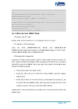
Page 18: ...the NAND Flash use the following steps Preparation 1 Format the TF card to a FAT or FAT32 file system using the HP USB Disk Storage Format Tool 2 Copy all the image files under linux image of the CD...

Page 19: ...30 run updatesys NAND erase device 0 whole chip Erasing at 0x1ffe0000 100 complete OK mmc1 is available reading x load bin ift_for_NAND 10912 bytes read HW ECC selected NAND write device 0 offset 0x0...

Page 20: ...oot up from the TF card 1 Format the TF card Please refer to contents of 3 1 1 Booting from a TF Card 2 Copy runtime image Copy the MLO EBOOTSD nb0 and NK bin image files located in CD WINCE600 image...

Page 21: ...does not exist Formatting flash Flash format complete Forcing cold boot non persistent registry and other data will be wiped Hit space to enter configuration menu 5 Hit space to enter configuration m...

Page 22: ...TSD nb0 image files located in CD WINCE600 image to the TF card rename EBOOTNAND nb0 to EBOOTND nb0 3 Flashing the image file Insert the TF card and reboot the system The system will boot from the TF...

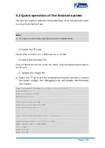
Page 23: ...er linux demo Android image to the TF card 3 Update the image file a Insert the TF card into the development board and then connect the power supply the debugging tool will display the following infor...

Page 24: ...ding x load bin ift_for_NAND 11000 bytes read HW ECC selected NAND write device 0 offset 0x0 size 0x2af8 12288 bytes written OK reading flash uboot bin 230740 bytes read SW ECC selected NAND write dev...

Page 25: ...er programming is complete once this happens you can remove the TF card c Restart the board to boot the Android OS d The default display mode is a 4 3 LCD This can be changed by referring to 4 8 1 Sel...

Page 26: ...nit unpainted metal chassis If possible use antistatic devices such as wrist straps and floor mats Always hold an evaluation board by its edges Avoid touching the contacts and components on the board...

Page 27: ...insists on a simple business model to offer customers high performance low cost products with the best quality and service 2 1 Technical support service Embest provides one year of free technical sup...

Page 28: ...nconsistent with their specification Products are subject to damage in either appearance or function due to natural disasters flood fire earthquake lightning strike or typhoon or natural aging of comp...

Page 29: ...will not take any responsibility for products returned without the prior permission of the company 2 3 Basic guidelines for protection and maintenance of LCDs 1 Do not use finger nails or other hard...

Page 30: ...as serial ports USB interface devices and LCD screens Control system transplantation BSP driver development API software development Other value added services including supply of power adapters and...

Reviews: