background image

www.mounts.com  |  North America  800.368.9700  | Interna1-714-632-7100

Warning Statements

Weight Limit

Maximum Weight: 

60 lbs.

AVERTISSEMENT

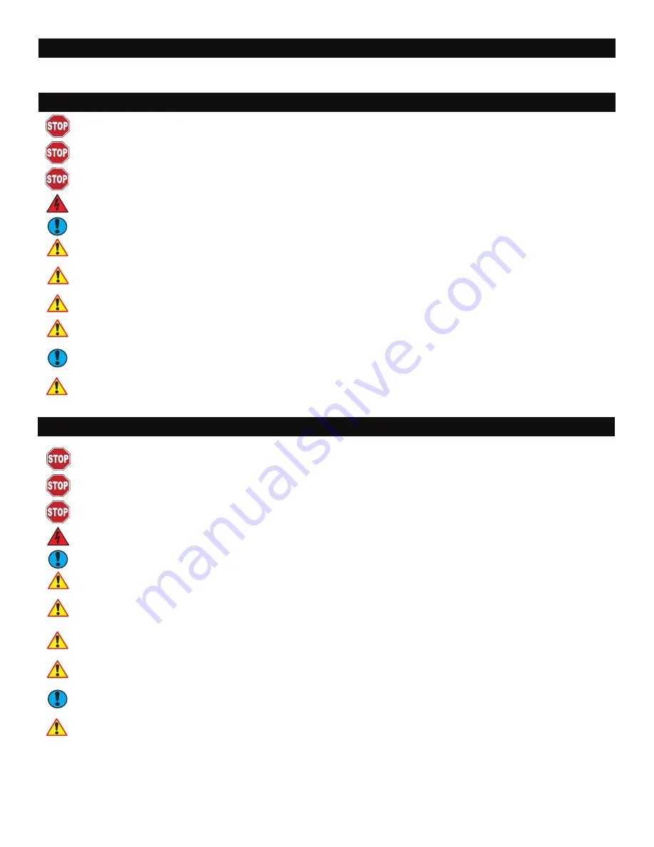
THE CEILING STRUCTURE MUST BE CAPABLE OF SUPPORTING 60 LBS. IF NOT, THE CEILING MUST BE REINFORCED. PROPER INSTALLATION PROCEDURE IS A 

QUALIFIED SERVICE TECHNICIAN, AS OUTLINED IN THE INSTALLATION INSTRUCTIONS, MUST BE ADHERED TO. FAILURE TO DO SO COULD RESULT IN SERIOUS 

PERSONAL INJURY, OR EVEN DEATH.

SAFETY MEASURES MUST BE PRACTICED AT ALL TIMES DURING THE INSTALLATION OF THIS PRODUCT. USE PROPER SAFETY GEAR AND TOOLS FOR THE 

INSTALLATION PROCEDURE TO PREVENT PERSONAL INJURY.

PRIOR TO THE INSTALLATION OF THIS PRODUCT, THE INSTALLATION INSTRUCTIONS SHOULD BE READ AND COMPLETELY UNDERSTOOD. THE INSTALLATION 

INSTRUCTIONS MUST BE READ TO PREVENT PERSONAL INJURY AND PROPERTY DAMAGE. KEEP THESE INSTALLATION INSTRUCTIONS IN AN EASILY ACCESSIBLE 

LOCATION FOR FUTURE REFERENCE.

Indicates that the power plug is to be disconnected from the power outlet 

Safety Precautions must be taken at all times

Warning and Caution statements.

A secure structure must support the weight, or load, of the projector. When mounting to a ceiling that contains wooden studs, dead center of the wooden stud must be confirmed prior to 

installation.

Do not install on a structure that is prone to vibration, movement or chance of impact. Failure to do so could result in damage to the projector and/or damage to the mounting surface.

Do not install near heater, fireplace, direct sunlight, air conditioning or any other source of direct heat energy. Failure to do so may result in damage to the projector and could increase 

the risk of fire.

At least two qualified people should perform the installation procedure. Injury and/or damage can result from dropping or mishandling the projector.

Recommended mounting surfaces: wooden studs and solid-flat concrete. If the mount is to be installed on any surface other than wooden studs, use suitable 

hardware (which is commercially available). 

LA STRUCTURE DE PLAFOND DOIT ÊTRE CAPABLE DE SOUTENIR 40 LIVRES. SINON, LE PLAFOND DOIT ÊTRE RENFORCÉ. LA PROCÉDURE D'INSTALLATION APPRO-

PRIÉE PAR UN TECHNICIEN DE SERVICE QUALIFIÉ, COMME INDIQUÉ DANS LES INSTRUCTIONS D'INSTALLATION, DOIT ÊTRE RESPECTÉE. LE NON-RESPECT DE CETTE 

CONSIGNE PEUT ENTRAÎNER DES BLESSURES GRAVES OU MÊME LA MORT.

DES MESURES DE SÉCURITÉ DOIVENT ÊTRE PRATIQUÉES À TOUT MOMENT PENDANT L'INSTALLATION DE CE PRODUIT. UTILISER DES ÉQUIPEMENTS DE PROTECTION 

ET DES OUTILS APPROPRIÉS POUR QUE LA PROCÉDURE D'INSTALLATION ÉVITE LES BLESSURES CORPORELS.

AVANT L'INSTALLATION DE CE PRODUIT, LES INSTRUCTIONS D'INSTALLATION DEVRAIENT ÊTRE LUES ET COMPRISES COMPLÈTEMENT. LES INSTRUCTIONS 

D'INSTALLATION DOIVENT ÊTRE LUES POUR EMPÊCHER LE DOMMAGE CORPOREL ET LES DÉGATS MATÉRIELS. MAINTENIR CES INSTRUCTIONS D'INSTALLATION DANS 

UN ENDROIT FACILEMENT ACCESSIBLE POUR RÉFÉRENCE ULTÉRIEURE. 

Indique que la prise de courant doit être débranchée de la sortie de puissance.

Les mesures de sécurité doivent être prises à tout moment.

Messages d’avertissement et de mise en garde.

Une structure sécurisée doit soutenir le poids, ou la charge, du projecteur. En montant à un plafond qui contient les goujons en bois, le centre mort du goujon en bois doit être confirmé 

avant l'installation.

Ne pas installer sur une structure qui est sujet aux vibrations, à la circulation ou la chance de l'impact. Tout manquement à ce règlement pourrait avoir comme conséquence des dom-

mages au projecteur et/ou des dommages à la surface de montage. 

Éviter d’installer dans la proximité des appareils de chauffage, cheminées, rayonnement solaire direct, conditionnement d’air ou d’autres sources d’énergie thermique directe. Le défaut 

de le faire pourrait endommager l’écran et pourrait augmenter le risque d’incendie. 

Au moins deux personnes qualifiées devraient exécuter la procédure d'installation. Les dommages et/ou les dommages peuvent résulter de laisser tomber ou de traiter mal le projecteur. 

Surfaces de montage recommandées : goujons en bois et béton plein-plat. Si le bâti doit être installé sur n'importe quelle surface autre que les goujons en bois, utiliser le matériel ap-

proprié (qui est disponible commercialement).

Summary of Contents for PBC- UMW

Page 1: ... International 1 714 632 7100 1321 S State College Blvd Fullerton CA 92831 USA Installation Guide Installationsanleitung Guía de Instalacíon Guida de Installazione Guide d Installation Installatie gids PBC UM SERIES PBC UMW White PBC UMS Black ...

Page 2: ...UCTURE DE PLAFOND DOIT ÊTRE CAPABLE DE SOUTENIR 40 LIVRES SINON LE PLAFOND DOIT ÊTRE RENFORCÉ LA PROCÉDURE D INSTALLATION APPRO PRIÉE PAR UN TECHNICIEN DE SERVICE QUALIFIÉ COMME INDIQUÉ DANS LES INSTRUCTIONS D INSTALLATION DOIT ÊTRE RESPECTÉE LE NON RESPECT DE CETTE CONSIGNE PEUT ENTRAÎNER DES BLESSURES GRAVES OU MÊME LA MORT DES MESURES DE SÉCURITÉ DOIVENT ÊTRE PRATIQUÉES À TOUT MOMENT PENDANT L ...

Page 3: ...any combination of single and dual legs together as show in Options 1 and 2 The number of legs may vary depending on the number of mounting points found on the bottom of the projector A Single Wooden Stud Mounts B Solid Structure Mounting Points C M3 Security Allen Wrench D Security Allen Wrench E 1 5 nipple NTP F Tension Knobs G Safety Knob H Security Screws I Leveling Screws J Universal Mounting...

Page 4: ...omme conséquence des dommages corporels sérieux et peut éventuellement endommager le projecteur LE PROJECTEUR EST FRAGILE MANIPULER AVEC SOIN À TOUT MOMENT Passer en revue le manuel d exploitation de la fabrication de projecteurs et se référer à la section de support de plafond dans le manuel de l opérateur Ici vous trouverez normalement des informations de référence importantes concernant des dim...

Page 5: ...sembly and the upper section tri lock assembly points Figure 2A and 2B Step 4 Loosen the security screw knurl knob far enough to allow the two parts to be rotated 180º apart and separate Figure 2C Figure 2 Mount Preparation A B C Tension Knobs Upper Assembly Safety Knob Tri Lock Opening Rotate 180 To unlock Installation Guide Installationsanleitung Guía de Instalacíon Guida de Installazione Guide ...

Page 6: ...ng legs Step 2 Select the mounting hardware that the projector requires and loosely install the universal mount on the projector Attachez uniquement aux points de montage spécifiques du fabricant de projecteur sur le châssis du projecteur avec un minimum de trios pattes de fixation Veuillez suivre toutes les instructions de séurité spécifiés par le fabricant de projecteur aussi bien que les instru...

Page 7: ...ire vous risquez d endommager les filetages dans le projecteur Step 1 Rotate the leveling barrels to level the mounting bracket Step 2 Position the mounting bracket so that it avoids most if not all ventilation points including lamp and filter access doors Step 3 When the desired position is achieved tighten the mounting screws to the projector and then tighten the security hex head leg screw with...

Page 8: ...n location o o Identify the center of the ceiling stud p p Use a pencil to mark the location of the ceiling stud center Minimum of 2 X 4 wood stud to be used Minimum de 2 X 4 bois goujon pour être utilisé n n Use a pencil and mark 2 mounting hole locations through the slots Installation Guide Installationsanleitung Guía de Instalacíon Guida de Installazione Guide d Installation Installatie gids PB...

Page 9: ...he mounting screws Éviter de trop serrer les vis de montage Step 4 Step 3 Drill a pilot hole in the center using a 1 8 drill bit and power drill Only use a 1 8 drill bit when drilling the pilot holes N utiliser qu un foret de 1 8 lors du forage de guidage Installation Guide Installationsanleitung Guía de Instalacíon Guida de Installazione Guide d Installation Installatie gids PBC UM SERIES ...

Page 10: ...e base of the upper assembly Step 2 Carefully lift the projector and insert the mounting bracket mating special tri lock cutout into the mating portion of the upper assembly Step 3 Once inserted rotate the projector and mounting bracket 180º and secure the rear safety knob first to prevent further rotation of the bracket in the upper assembly Step 4 Tighten the remaining two tension knurl knobs un...

Page 11: ...ilt angle of the projector slightly loosen the side M8 screws and tilt to the desired angle and firmly tighten the two M8 adjustments screws C If roll adjustment is needed to square the images on the screen slightly loosen the front and rear M8 screws and adjust to the desired angle The firmly tighten the two M8 adjustment screws Re check the hardware for tightness and security Figure 7 Final Adju...

Page 12: ...p Installation Step 1 Once all the final adjustments have been finished install the plastic caps on the leveling barrels Figure 8 Plastic Cap Installation Installation Guide Installationsanleitung Guía de Instalacíon Guida de Installazione Guide d Installation Installatie gids PBC UM SERIES ...

Page 13: ...14 632 7100 All measurements are in inches mm Technical Specifications Figure 9 Technical Dimensions 1 5 NPT Nipple Security Installation Guide Installationsanleitung Guía de Instalacíon Guida de Installazione Guide d Installation Installatie gids PBC UM SERIES ...

Page 14: ...damage to mounts adapters displays projectors other property or personal injury resulting in whole or in part from improper installation modification use or misuse of its products NOTWITHSTANDING ANYTHING TO THE CONTRARY IN THIS WARRANTY THIS WARRANTY IS LIMITED TO FIVE YEARS FROM THE DATE OF PURCHASE IN THE EVENT THAT THE WAR RANTED PRODUCT IS COMMERCIALLY RENTED OUT Electrical products and compo...

Reviews: