background image

1/8" Drill bit

#14  x 2" Wood

Screw

x 1

x 3

M2.5 x 10mm

x 4

M3 x 12mm

x 4

M4 x 12mm

x 4

M5 x 12mm

M6 x 12mm

M6 x 25mm

x 4

x 4

x 1

5/8 Barrel Cap

M5 Security 

Allen Key

Green Level

x 4

x 1

x 1

x 1

M3 Security 

Allen Key

x 1

www.mounts.com  |  North America  800.368.9700  | Interna1-714-632-7100

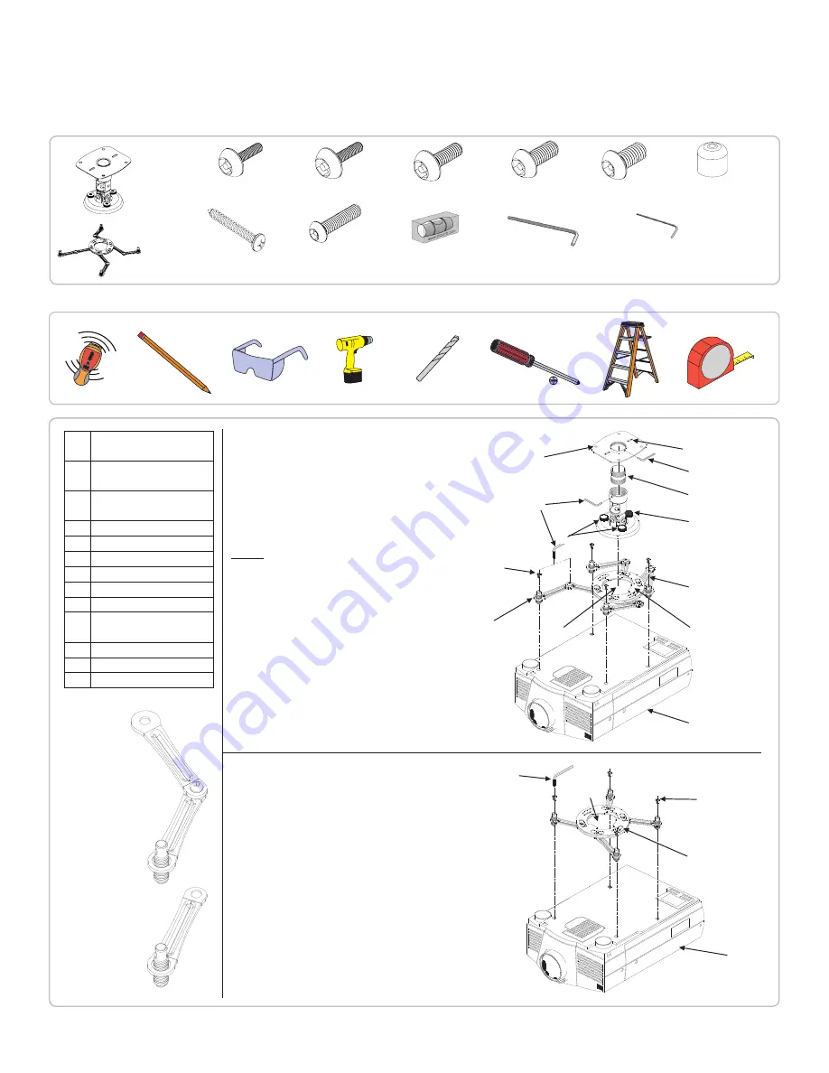
A Single Wooden Stud 

Mounts

B

Solid Structure 

Mounting Points

C

Ceiling Plate

D Security Allen Wrench

E

Extension

F

Tension Knobs

G Safety Knob

H Security Screws

I

Leveling Screws

J

Universal Mounting 

bracket

K Leg Assembly

L

Projector (not included)

M Tri-Lock Opening

NOTE

:  The four (two-piece) 

leg assemblies can be used as 

single leg or any combination 

together as shown in Options 

1 and 2. The number of legs 

may  vary  depending  on  the 

projector.

D

D

M

H

J

L

L

J

B

K

G

E

C

M

I

H

F

Option 2

Option 1

Single Leg

Combination 

Leg

Note: The four (two piece)

leg assemblies can be used 

as single leg or any combination 

of single and dual legs together 

as show in Options 1 and 2. The 

number of legs may vary 

depending on the number of 

mounting points found on the 

bottom of the projector. 

A

Single Wooden Stud 

Mounts

B

Solid Structure 

Mounting Points

C

M3 Security Allen 

Wrench

D

Security Allen Wrench

E

1.5” nipple (NTP)

F

Tension Knobs

G

Safety Knob

H

Security Screws

I

Leveling Screws

J

Universal Mounting 

bracket

K

Leg Assembly

L

Projector (not included)

M Tri-Lock Opening

H

J

L

L

J

A

B

K

G

E

C

M

I

H

F

Option 2

Option 1

D

D

M

Single Leg

Combination 

Leg

A

Single Wooden Stud 

Mounts

B

Solid Structure 

Mounting Points

C

M3 Security Allen 

Wrench

D

Security Allen Wrench

E

1.5” nipple (NTP)

F

Tension Knobs

G

Safety Knob

H

Security Screws

I

Leveling Screws

J

Universal Mounting 

bracket

K

Leg Assembly

L

Projector (not included)

M

Tri-Lock Opening

H

J

L

L

J

A

B

K

G

E

C

M

I

H

F

Option 2

Option 1

D

D

M

Single Leg

Combination 

Leg

Installation Guide

Installationsanleitung, Guía de Instalacíon, Guida de Installazione, Guide d’Installation, Installatie gids

PBC-UM SERIES

Included components

Required for installation

Summary of Contents for PBC- UMW

Page 1: ... International 1 714 632 7100 1321 S State College Blvd Fullerton CA 92831 USA Installation Guide Installationsanleitung Guía de Instalacíon Guida de Installazione Guide d Installation Installatie gids PBC UM SERIES PBC UMW White PBC UMS Black ...

Page 2: ...UCTURE DE PLAFOND DOIT ÊTRE CAPABLE DE SOUTENIR 40 LIVRES SINON LE PLAFOND DOIT ÊTRE RENFORCÉ LA PROCÉDURE D INSTALLATION APPRO PRIÉE PAR UN TECHNICIEN DE SERVICE QUALIFIÉ COMME INDIQUÉ DANS LES INSTRUCTIONS D INSTALLATION DOIT ÊTRE RESPECTÉE LE NON RESPECT DE CETTE CONSIGNE PEUT ENTRAÎNER DES BLESSURES GRAVES OU MÊME LA MORT DES MESURES DE SÉCURITÉ DOIVENT ÊTRE PRATIQUÉES À TOUT MOMENT PENDANT L ...

Page 3: ...any combination of single and dual legs together as show in Options 1 and 2 The number of legs may vary depending on the number of mounting points found on the bottom of the projector A Single Wooden Stud Mounts B Solid Structure Mounting Points C M3 Security Allen Wrench D Security Allen Wrench E 1 5 nipple NTP F Tension Knobs G Safety Knob H Security Screws I Leveling Screws J Universal Mounting...

Page 4: ...omme conséquence des dommages corporels sérieux et peut éventuellement endommager le projecteur LE PROJECTEUR EST FRAGILE MANIPULER AVEC SOIN À TOUT MOMENT Passer en revue le manuel d exploitation de la fabrication de projecteurs et se référer à la section de support de plafond dans le manuel de l opérateur Ici vous trouverez normalement des informations de référence importantes concernant des dim...

Page 5: ...sembly and the upper section tri lock assembly points Figure 2A and 2B Step 4 Loosen the security screw knurl knob far enough to allow the two parts to be rotated 180º apart and separate Figure 2C Figure 2 Mount Preparation A B C Tension Knobs Upper Assembly Safety Knob Tri Lock Opening Rotate 180 To unlock Installation Guide Installationsanleitung Guía de Instalacíon Guida de Installazione Guide ...

Page 6: ...ng legs Step 2 Select the mounting hardware that the projector requires and loosely install the universal mount on the projector Attachez uniquement aux points de montage spécifiques du fabricant de projecteur sur le châssis du projecteur avec un minimum de trios pattes de fixation Veuillez suivre toutes les instructions de séurité spécifiés par le fabricant de projecteur aussi bien que les instru...

Page 7: ...ire vous risquez d endommager les filetages dans le projecteur Step 1 Rotate the leveling barrels to level the mounting bracket Step 2 Position the mounting bracket so that it avoids most if not all ventilation points including lamp and filter access doors Step 3 When the desired position is achieved tighten the mounting screws to the projector and then tighten the security hex head leg screw with...

Page 8: ...n location o o Identify the center of the ceiling stud p p Use a pencil to mark the location of the ceiling stud center Minimum of 2 X 4 wood stud to be used Minimum de 2 X 4 bois goujon pour être utilisé n n Use a pencil and mark 2 mounting hole locations through the slots Installation Guide Installationsanleitung Guía de Instalacíon Guida de Installazione Guide d Installation Installatie gids PB...

Page 9: ...he mounting screws Éviter de trop serrer les vis de montage Step 4 Step 3 Drill a pilot hole in the center using a 1 8 drill bit and power drill Only use a 1 8 drill bit when drilling the pilot holes N utiliser qu un foret de 1 8 lors du forage de guidage Installation Guide Installationsanleitung Guía de Instalacíon Guida de Installazione Guide d Installation Installatie gids PBC UM SERIES ...

Page 10: ...e base of the upper assembly Step 2 Carefully lift the projector and insert the mounting bracket mating special tri lock cutout into the mating portion of the upper assembly Step 3 Once inserted rotate the projector and mounting bracket 180º and secure the rear safety knob first to prevent further rotation of the bracket in the upper assembly Step 4 Tighten the remaining two tension knurl knobs un...

Page 11: ...ilt angle of the projector slightly loosen the side M8 screws and tilt to the desired angle and firmly tighten the two M8 adjustments screws C If roll adjustment is needed to square the images on the screen slightly loosen the front and rear M8 screws and adjust to the desired angle The firmly tighten the two M8 adjustment screws Re check the hardware for tightness and security Figure 7 Final Adju...

Page 12: ...p Installation Step 1 Once all the final adjustments have been finished install the plastic caps on the leveling barrels Figure 8 Plastic Cap Installation Installation Guide Installationsanleitung Guía de Instalacíon Guida de Installazione Guide d Installation Installatie gids PBC UM SERIES ...

Page 13: ...14 632 7100 All measurements are in inches mm Technical Specifications Figure 9 Technical Dimensions 1 5 NPT Nipple Security Installation Guide Installationsanleitung Guía de Instalacíon Guida de Installazione Guide d Installation Installatie gids PBC UM SERIES ...

Page 14: ...damage to mounts adapters displays projectors other property or personal injury resulting in whole or in part from improper installation modification use or misuse of its products NOTWITHSTANDING ANYTHING TO THE CONTRARY IN THIS WARRANTY THIS WARRANTY IS LIMITED TO FIVE YEARS FROM THE DATE OF PURCHASE IN THE EVENT THAT THE WAR RANTED PRODUCT IS COMMERCIALLY RENTED OUT Electrical products and compo...

Reviews: