background image

WMK-027

Universal Short Throw Wall Mount

NORTH AMERICA

3130 East Miraloma Avenue

Anaheim, CA 92806 USA

USA and Canada –

Phone: 800-368-9700

Fax: 800-832-4888

EUROPE

Swallow House, 

Shilton Industrial Estate,

Shilton, Coventry, England CV79JY

Phone: +44 (0) 2476 614700

Fax: +44 (0) 2476 614710

Other Locations – Phone: (001)-714-632-7100; Fax: (001)-714-632-1044

©Premier Mounts 2009

9530-070-353-00

INSTALLATION INSTRUCTIONS

ViewSonic by Premier Mounts

Summary of Contents for WMK-027

Page 1: ...ada Phone 800 368 9700 Fax 800 832 4888 EUROPE Swallow House Shilton Industrial Estate Shilton Coventry England CV79JY Phone 44 0 2476 614700 Fax 44 0 2476 614710 Other Locations Phone 001 714 632 710...

Page 2: ...e stud finder is recommended Be aware of the mounting environment If drilling and or cutting into the mounting surface always make sure that there are no electrical wires in wall Cutting drilling into...

Page 3: ...ty Head Screws Qty 11 Inner Slide Plate Qty 1 3 8 Concrete Wedge Anchors Qty 4 5 16 x 3 Lag Bolts Qty 4 5 16 Flat Washers Qty 4 Installation Tools not supplied Phillips Screwdriver 1 4 Drill Bit Elect...

Page 4: ...User s Manual to determine the offset of the projector lens to the top of the screen whiteboard Lens PDS PLUS Bracket Projector In order to determine the installation height and throw distance the PD...

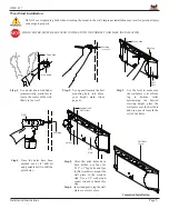
Page 5: ...l to mark the rest of the holes Wood Stud Stud finder Marking from page 4 Wood Stud Marking Wall Plate Do NOT over tighten lag bolts when attaching the mount to the wall Improper installation may resu...

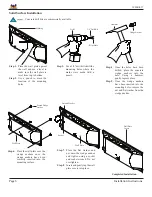
Page 6: ...the hole Using a hammer gently tap into place Step 5 Once the wedge anchors have been inserted into the mounting holes remove the nut and flat washer from the wedge anchor Marking Drill Pilot Hole Ha...

Page 7: ...orage door that is located on the side of the wall plate Step 2 Place the electronic components inside the storage enclosure Step 3 Make all electronic connections at this time Step 4 Close the storag...

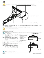
Page 8: ...btract disance Y from the distance listed Step 4 Use a tape measure to mark the appropriate distance on the WMK 027 This will be where the center of the mounting bracket will be located WMK 027 MAKE S...

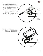
Page 9: ...nting holes of the upper projector plate with the mounting holes of the inner slide plate Step 5 Secure and finger tighten two 2 M6 x 12mm security head screws Step 6 Once the correct throw distance h...

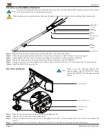
Page 10: ...he WMK 027 the front of the mount Step 2 Attach the upper mounting bracket directly to the extension using two 2 M6 x 12mm set screws see page 8 Step 3 Adjust length so that the center of the upper mo...

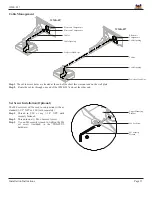
Page 11: ...ort throw mount and on the wall plate Step 2 Route the cables through one end of the WMK 027 and out the other end Set Screw Installation Optional The M6 set screw will be used in conjunction with any...

Page 12: ...WMK 027 Page 12 Installation Instructions Technical Specifications All measurements are in inches mm...

Page 13: ...FITNESS FOR A PARTICULAR PURPOSE PREMIER MOUNTS IS NOT RESPONSIBLE FOR INCIDENTAL OR CONSEQUENTIAL DAMAGES INCLUD ING BUT NOT LIMITED TO INABILITY TO USE ITS PRODUCTS OR LABOR COSTS FOR REMOV ING AND...

Reviews: