background image


INSTALLATION INSTRUCTIONS 

MOBILE HOME INSTALLATION 

The installation of this range must conform with the Manufactured Home Construction and Safety Standards, Title 24 CFR, Part 
3280 (formerly the Federal Standard for Mobile Home Construction and Safety, Title 24, HUD (Part 280) or, when such standard 
is not applicable, the Standard for Manufactured Home Installation, ANSI A 225.1/NFPA 501A, or with local codes.  When this 

range is installed in a mobile home, it must be secured to the floor during transit.  Any method of securing the range is adequate 
as long as it conforms to the standards listed above. 

ELECTRICAL CONNECTIONS TO THE RANGE 

Use  only  a  3-conductor,  or  if  required  a  4-conductor  range  cord.    The  range  power-supply  cord  used  must  be  rated                             
250 Volts 40 Amperes and marked for use with ranges.  The range power-supply cord must have open end spade lugs with 
upturned ends or closed-loop terminals. 


NOTE:  A 4-conductor cord is to be used only when the appliance is installed in a  
mobile home or where local codes do not permit grounding through the neutral. 

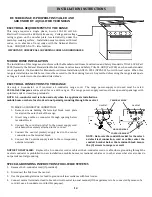
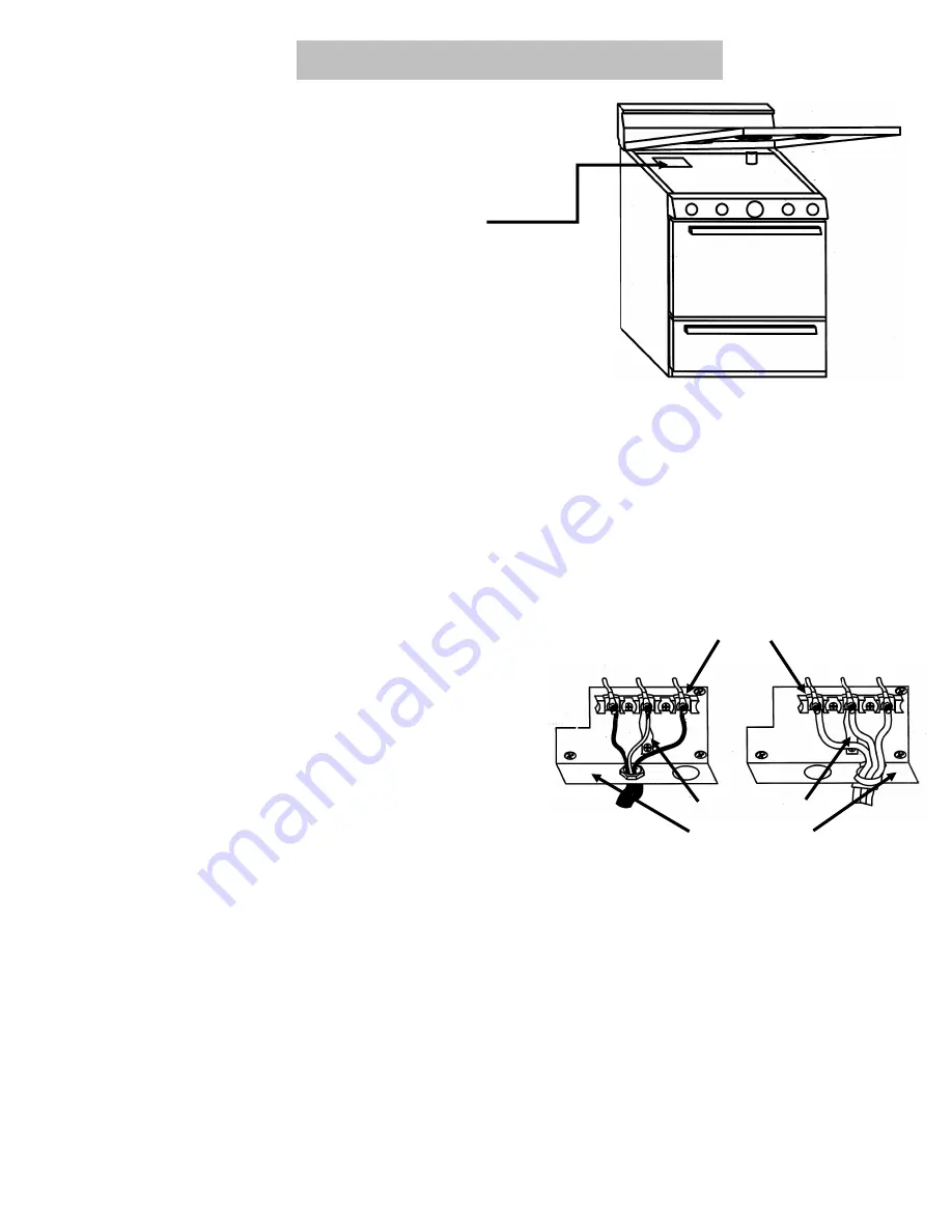
TO MAKE A 3-CONDUCTOR CONNECTION: 
1.  Remove  screws  holding  the  terminal  block  cover  plate 

located on the outer back of the range. 

2.  Insert  range  cable  or  connector  through  opening  below 

terminal block. 

3.  Connect  the  cord  strain  relief  to  the  power  supply  cord 

which must be securely attached to the cord set. 

4.  Connect  the  neutral  (center)  supply  lead  to  the  center    

connection on the terminal block. 

5.  Connect the 2 outside supply leads to the corresponding 

outside terminals. 


neutral 

neutral 

TERMINAL BLOCK 

GROUND STRAP  

NOTE:  Re-locate the conduit bracket for the select-
ed electrical  connection, cord  or cable, center  the 

conduit  bracket  below  the  terminal  block  Secure 
the (3) screws to range rear wall. 

CONDUIT BRACKET 

NOTICE TO INSTALLER:    Replace the 3-conductor cord or cable with a 4-conductor cord or cable where grounding through the 
neutral conductor is prohibited in new installations, mobile homes, recreational vehicles or in other areas where local codes do 

not permit neutral grounding. 

SPECIAL GROUNDING INSTRUCTIONS FOR 4-WIRE SYSTEMS 

1.  Remove the 3-conductor cord (if provided). 

2.  Disconnect the link from the neutral. 

3.  Use the grounding terminal or lead to ground unit in accordance with local codes. 

4.  Connect neutral terminal or lead to branch circuit neutral in usual manner (If the appliance is to be connected by means of a 

cord kit, use a 4-conductor cord for this purpose). 

BE SURE RANGE IS PROPERLY INSTALLED AND 

GROUNDED BY A QUALIFIED TECHNICIAN 


ELECTRICAL REQUIREMENTS TO THE RANGE 

This  range  requires  a  single  phase,  3-wire  120-240  volt  A.C.     
Electrical Circuit with a 60 Hertz frequency.  Voltage and wattage 

rating  is  given  on  the  number  plate,  located  directly  under  the 
main  top  cooking  surface.    Installation  must  conform  with  local 
codes,  or,  in  absence  of  local  codes,  with  the  National  Electric 

Code,    ANSI/NFPA No. 70– latest edition. 

IMPORTANT: OBSERVE ALL GOVERNING CODES AND ORDINANCES. 

14 

Summary of Contents for ECS2X0BP

Page 1: ...ime some models 6 7 Outlet Circuit Breaker 7 Appliance Outlet some models 7 Care and Cleaning 7 10 Installation Backguard Installation 11 12 Maximum and Minimum Clearances 13 Electrical Installation 1...

Page 2: ...nge doors could create a hazard 3 CAUTION KEEP CHILDREN AND PETS AWAY FROM THE RANGE AT ALL TIMES Do Not Leave Children Alone Chil dren should not be left alone or unattended in an area where an appli...

Page 3: ...HEATING ELEMENTS Heating element should never be immersed in water 17 MAKE SURE REFLECTOR PANS OR DRIP BOWLS ARE IN PLACE Absence of these pans or bowls during cooking may subject wiring or component...

Page 4: ...s 20 MODELS 24 AND 30 MODELS Pans should have tight fitting lids to hold steam within the pans and reduce cooking time Pans sizes should be matched to the size of the surface element Large pans and sk...

Page 5: ...us cookware may give more favorable results when cooking on a smooth top glass cooking surface Aluminum Very good heat conductor resulting in good heat transfer from top to pan Sliding aluminum pans a...

Page 6: ...oven turn the oven control dial clockwise to the desired temperature DO NOT TURN TO THE BROIL SETTING AND THEN BACK TO THE DESIRED TEMPERATURE When the control is turned on the bake element turns to f...

Page 7: ...ns on the same rack using the second rack position from the bottom When four cakes or pies are baked at the same time place two pans on each rack using the second and fourth rack positions from the bo...

Page 8: ...ooks meat to an appetizing brown without undue loss of juices and minimum shrinkage It also reduces spattering and keeps oven cleanup at a minimum STAND AWAY FROM THE RANGE WHEN OPENING THE DOOR OF A...

Page 9: ...meats and personal preferences may make changes necessary DO NOT USE THE BROILER PAN WITHOUT ITS INSERT NEVER COVER THE BROILER INSERT OPENINGS WITH ALUMINUM FOIL IF THE INSERT IS COVERED BY ALUMINUM...

Page 10: ...inish and is a type of glass fused to metal With proper care the porcelain enamel walls in these ovens will retain their good looking finish for many years Food soil that is allowed to harden and bake...

Page 11: ...s steel or chrome are recommended Bluish stains on these materials are caused by overheating and cannot be removed Do not use steel wool abrasives ammonia acids or commercial oven cleaners PORCELAIN E...

Page 12: ...tergent and water DO NOT USE STEEL WOOL TO REMOVE REFLECTOR PANS The chrome reflector pans are removed by first removing the element See To Remove Surface Elements and then lifting the reflector pan o...

Page 13: ...AREA BENEATH THE COOKTOP STORAGE DRAWER on some models The storage drawer can be removed for easier Cleaning To remove 1 Pull drawer out to the stop position 2 Push up under the center of the drawer w...

Page 14: ...Place the main top on the pins Lift the front of the main top and thread the two nuts on the hinge pins Place the main top in the normal position FORMED METAL ENDS BACKGUARD INSTALLA TION Ceramic gla...

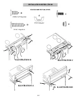
Page 15: ...NSTALLATION INSTRUCTIONS 8 18 x 5 8 long screw 10 x 1 long screw 10 24 wing nut A B C D E BACKGUARD INSTALLATION C A C E E D D A F F B D D B ILLUSTRATION A ILLUSTRATION B ILLUSTRATION C ILLUSTRATION D...

Page 16: ...al below the cooking top The back of the range can be flush to combustible material Zero clearance is permitted between the range and combustible construction extending from the cooking surface to 18...

Page 17: ...eutral center supply lead to the center connection on the terminal block 5 Connect the 2 outside supply leads to the corresponding outside terminals neutral neutral TERMINAL BLOCK GROUND STRAP NOTE Re...

Page 18: ...e side of the cabinet sitting to the right side of the range If there are no adjacent cabinets align Edge B of the bracket with the edge of the range side After the bracket has been placed mark the ho...

Page 19: ...ges only OVEN TEMPERATURE TOO HOT OR TOO COLD Oven Thermostat Control operation in the Broil Mode Turn Oven Control to OFF and reset Oven Control rotating from OFF to the desired temperature BAKE ELEM...

Page 20: ..._________________________________________________ Installation Date_______________________________________________________________ Dealer s Name and Address ___________________________________________...

Reviews: