1-6
Alarm Cards
Model No.
Running Head
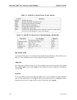
Alarm Card Descriptions
Alarm Cards
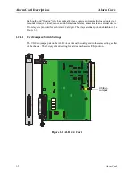
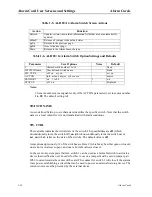
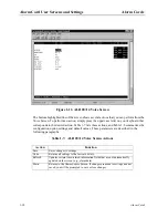
U.S./European Voltage Jumpers
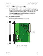
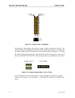
You can configure the ALR 28+14 Card for either U.S. or European operation by moving the
jumpers located on JP64. One jumper is provided for each alarm sensor on the card. Inserting
a jumper on the left-side two pins selects U.S. voltages. Inserting the jumper on the right-side
two pins selects European voltages. All jumpers should be set to the same position, and this
setting should match the configuration of the system chassis for the card to work properly. The
factory default jumper setting is US.
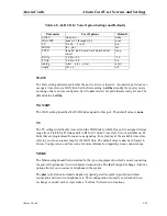
Voltage Control Switches
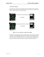
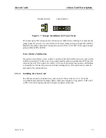
Use switches S1 and S2 to control the voltage supplied to each group of active sensors. When
either switch is set to SYS, the board su12 and -12 VDC power to the sensor group
associated with that Amphenol connector. When a switch is set to BAT, the ALR 28+14 Card
supplies external telco power to the sensors in that group.
You can set the switches individually (i.e., one can be set to SYS and the other to BAT).
However, this will affect all 14 sensors in the respective group.
Switch S1 controls the sensors on the J3 (lower) connector, and switch S2 controls the sensors
on the J4 (upper) connector.
The factory default setting for the voltage control switches is SYS.
Summary of Contents for ALR 28+14
Page 1: ...Alarm Cards Reference Guide Publication 999 001967 Revision A1 Release 3 9 October 1999 ...
Page 4: ...Model No Running Head ...
Page 6: ...ii Alarm Cards Model No Running Head Contents ...
Page 8: ...iv Alarm Cards Model No Running Head Figures ...
Page 10: ...vi Alarm Cards Model No Running Head Tables ...
Page 34: ...1 24 Alarm Cards Model No Running Head Alarm Card Troubleshooting Alarm Cards ...

