1-20
Alarm Cards
Model No.
Running Head
Alarm Card User Screens and Settings
Alarm Cards
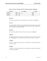
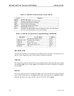
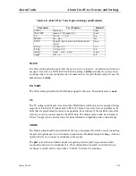
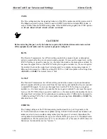
TYPE
The Type setting matches the signaling behavior of the FXS equipment and the remote switch.
The loop (Loop-start) option, which is used with POTS stations and simple PBX trunks, is
only available when the MODE setting is fxs. If the MODE setting is plar, the TYPE options
are d3-m1, d4-m1, d3-m2, d4-m2, d3-m3, and d4-m3.
CAUTION!
Before activating this port, verify the behavior expected by both the station and remote central
office equipment, and make sure the system is properly configured.
Rx TL
The Receive Transmission Level Point setting controls the amount of gain or attenuation
added to signals after they are decoded to analog signals. To increase the signal level, set the
RX TLP setting to a positive number (i.e., the larger the number, the more gain is added). To
decrease the signal level, set the RX TLP setting to a negative number (i.e., the more negative
the number, the more the signal level is decreased). For example, an incoming signal at -5
dBm can be increased to -3 dBm by setting RX TLP to +2 dB. Acceptable values range from
-10.0 dB to +2.0 dB. The default value is -5.0.
Tx TLP
The Transmit Transmission Level Point setting controls the amount of gain or attenuation
added to signals after they are received from the local analog port and before they are encoded
to digital PCM signals. To increase the signal level, set the TX TLP setting to a negative
number (i.e., the more negative the number, the more gain is added). To decrease the signal
level, set the TX TLP setting to a positive number (i.e., the more positive the number, the more
the signal level is decreased). For example, an incoming signal at -5 dBm can be increased to
-2 dBm by setting TX TLP to -3 dB. Acceptable values range from -10.0 dB to +5.0 dB. The
default value is +2.0.
CODING
The Coding setting sets the PCM companding method used for a port. In general, in the
T1/North American environment use µ-law coding. In the E1/International environment, use
a-inv (inverted A-law) or a-law coding; a-inv provides greater 1s density than a-law. The
coding default is determined by the type of card in the WAN port you select. The default value
is u-law (Note: On the system screens, "u" is used in place of "µ" because of ASCII character
limitations, but should be read as "mu-law.").
Summary of Contents for ALR 28+14
Page 1: ...Alarm Cards Reference Guide Publication 999 001967 Revision A1 Release 3 9 October 1999 ...
Page 4: ...Model No Running Head ...
Page 6: ...ii Alarm Cards Model No Running Head Contents ...
Page 8: ...iv Alarm Cards Model No Running Head Figures ...
Page 10: ...vi Alarm Cards Model No Running Head Tables ...
Page 34: ...1 24 Alarm Cards Model No Running Head Alarm Card Troubleshooting Alarm Cards ...


