background image

Appendix


36

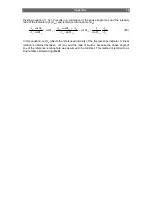
Dividing equation 11 by 12 results in a correlation of the phase angle (

Φ

m

) and the intensity 

ratio of the indicator dye (A

ind

) and reference luminophore (A

ref

) : 

ref

ind

ref

ref

ref

ref

ind

ref

ref

m

m

m

m

m

A

A

A

A

A

A

A

Φ

+

Φ

=

Φ

+

Φ

=

Φ

=

Φ

Φ

sin

1

cot

sin

cos

cot

sin

cos


(

13


In this equation, cot

Φ

m

 reflects the referenced intensity of the fluorescence indicator. A linear 

relation is obtained between  cot (

Φ

m

) and the ratio of A

ind

/A

ref

, because the phase angle of 

Φ

ref

 of the reference luminophore was assumed to be constant. This method is referred to as 

Dual Lifetime Referencing (

DLR

). 


Summary of Contents for pH-10 mini

Page 1: ...PreSens Precision Sensing GmbH Instruction Manual pH 10 mini 10 Channel Minisensor pH Meter ...

Page 2: ...0 mini 10 Channel Minisensor pH Meter Manual version 3 PC software version pH10 10_v6 PreSens Precision Sensing GmbH Josef Engert Strasse 11 D 93053 Regensburg Germany Phone 49 941 942 72 0 Fax 49 941 942 72 27 Email info PreSens de Internet www PreSens de ...

Page 3: ...sors 12 3 8 Response time 12 3 9 Housings of pH Sensitive Minisensors 12 3 9 1 Planar Analyte Sensitive Foils 13 3 9 2 Flow Through Cell pH Minisensor 14 4 Software 16 4 1 Software Installation 16 4 2 Starting pH 10 mini and its Software 18 4 3 Function and Description of the pH 10 mini Software 19 4 3 1 Menu Bar 19 4 3 2 Status Bar 20 4 3 3 Control section 20 4 3 4 Channel selection 23 4 3 5 Data...

Page 4: ...photo decomposition 29 7 2 Performance proof 29 8 General Instructions 30 8 1 Warm Up Time 30 8 2 Maintenance 30 8 3 Service 30 9 Technical Data General Data 31 9 1 Technical Notes 33 9 2 Operation Notes 33 10 Appendix 34 10 1 Dual Lifetime Referenced DLR Optical Sensors 34 ...

Page 5: ...tical pH sensors also called optodes have some important features They are small Their signal does not depend on the flow rate of the sample They can be physically divided from the measuring system which means a contactless measurement They are offered steril They can be used in disposables Therefore they are ideally suited for the examination of small sample volumes for highly parallelized measur...

Page 6: ...ied out by a suitable qualified technician trained by us Especially in the case of any damage to current carrying parts such as the power supply cable or the power supply itself the device must be taken out of operation and protected against being put back into operation If there is any reason to assume that the instrument can no longer be employed without a risk it must be set aside and appropria...

Page 7: ...training and experience the operators will know the necessary safety precautions to take when handling chemicals Keep the pH 10 mini power supply and optical sensors out of the reach of children As the manufacturer of the pH 10 mini we only consider ourselves responsible for safety and performance of the device if the device is strictly used according to the instruction manual and the safety guide...

Page 8: ...t The pH 10 mini is a precision pH meter designed for fiber optic pH minisensors For operation a PC Notebook with RS 232 interface is required The pH 10 mini is controlled using a comfortable software which also saves and visualizes the measured values 2 2 Front Panel of the pH 10 mini Device ...

Page 9: ...10 mini Device The electrical specifications of all rear panel connectors are given in the technical specification sheet Please read also the technical notes to avoid mistakes ELEMENT DESCRIPTION FUNCTION S1 ON OFF switch Switches the device ON and OFF C1 Line adapter for power supply Connector for 230 V AC power supply C2 RS 232 interface male Connect the device with a RS 232 data cable to your P...

Page 10: ... PC Notebook System requirements Windows XP Pentium processor at least 166 MHz 64 MB RAM A RS 232 port or a USB port and a USB serial adapter is needed RS 232 Cable Line adapter 110 220 V AC 12 V DC pH sensitive minisensors The minisensors are mounted into different types of housings scope of supply ...

Page 11: ...mic range Optical pH sensors respond according to the mass acting law hence they do not show a linear behaviour like potentiometric pH electrodes This limits their use to a dynamic range of approximately 3 to 4 pH units On the other hand the resolution can be very high in the optimal range A typical response curve of a pH sensor is shown below Increasing the pH decreases the phase angle Φ The phas...

Page 12: ...4 Cross sensitivities The optical pH measurement is interfered by ionic strength of the sample This can be overcome by a calibration with buffers of ionic strength similar to the sample 4 5 6 7 8 9 15 20 25 30 35 40 45 50 55 phase pH is50 is100 is200 Cross sensitivity to ionic strength A lower ionic strength than used in the calibration will pretend a lower pH and vice versa Also small fluorescent...

Page 13: ...rift is not getting smaller your signal drift is due to pH changes in your sample Drift due to bleaching 0 003 pH per 1000 measuring points 3 6 Temperature dependency pH Minisensors display as any other pH sensors a distinct temperature sensitivity Some typical calibration curves at different temperatures are shown below 4 5 6 7 8 9 10 15 20 25 30 35 40 45 50 55 Phase pH 5 C 15 C 20 C 30 C 35 C 40...

Page 14: ...luorescein or rhodamin in the sample The sensors can not be autoclaved but γ sterilized They do not stand pH above 9 and organic solvents 3 8 Response time The response time t90 of the pH sensor is dependent from the diffusion rate of protons through the sensor layer Hence the response time is dependent from the thickness of the sensor layer and the stirring rate The typical response t90 time of a...

Page 15: ...n destructive measurement from outside through the wall of the flask applicable in disposables No reference electrode needed pH measurement in the physiological range of pH 5 5 9 Resolution up to 0 005 Robust sensor with an excellent long term stability 0 1 pH within a week in 2 min mode Sterilizable by gamma irradiation Insensible towards electrical interference and magnetic fields Many disposabl...

Page 16: ...a diameter of 5 mm 3 9 1 Flow Through Cell pH minisensor Flow through cell pH minisensor FTC HP8 is a miniaturized fiber optic pH sensor integrated in a T shape flow through cell The FTC is connected to the PreSens pH meter pH 10 mini pH 4 mini or pH 1 mini by a polymer optical fiber POF with 2 mm diameter as a light guide The volume for liquid inside the FTC is about 300 microliters The standard ...

Page 17: ...t sensor with a good long term stability 0 1 pH within a week in 2 min mode Sterilizable by gamma irradiation Easy to handle Signal independent to flow velocity Insensible towards electrical interferences and magnetic fields This Flow Through Cell minisensor can be used in combination with the pH meter pH 1 mini pH 4 mini and pH 10 mini Order code for pH Flow Trough cells The order code key of the...

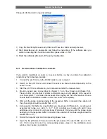
Page 18: ...tware Installation This software is compatible with Windows XP 1 Insert the supplied disc CD into the respective drive Start the file setup exe 2 Follow the instructions of the installation wizard 3 Choose the folder for installing the software ...

Page 19: ...General Instructions 17 Now the Software is properly installed and you will find a link in your Start menu ...

Page 20: ... your computer 2 Connect the power supply 3 Please close all other applications as they may interfere with the software Start the program pH10v10_6 4 The software is connecting to the instrument and uploading system information This may take a few minutes If the instrument is not switched on or not connected to the right com port an error message will occur Press OK and choose the right com port ...

Page 21: ... from all channels as well as the individual channel It is not possible to clear the graph window while a measurement is running The graph window is not cleared automatically after a new measurement is started Subsequent measurements can be displayed in the window PLEASE NOTICE It is not possible to store measurements without enabling logging The content of the graph can not be stored into a file ...

Page 22: ...played here The raw values amplitude and phase can be hidden by click hide raw value The color of the button near Phase Amplitude and ambient light indicates whether the readings are within the limits Whenever one of the buttons is red you will get an error message Usually the error is caused by the connection to the sensor 4 3 3 Control section Measurement and logging Here you can start a measure...

Page 23: ...create all button You will be asked to chose a filename Each Channel will be stored in a separate file The software will create files with the ending 01 txt to 10 txt Alternatively you can log each channel individually by activating the respective channel at the square on the right side ...

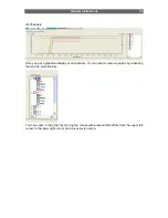
Page 24: ...a graphical display of all channels You can add or remove graphs by activating them at the selection bar You can zoom in the graph by moving the mouse with pressed left buttom from the upper left corner to the lower right corner and un zoom vice versa ...

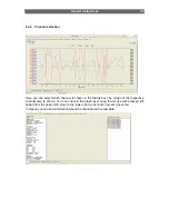
Page 25: ...own in the Status bar The Graph of the respective channel also is shown You can zoom in the graph by moving the mouse with pressed left button from the upper left corner to the lower right corner and un zoom vice versa In Report you can find information about the channel and the raw data ...

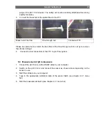
Page 26: ...re please do not place the vessel in a dry atmosphere Ensure proper ventilation if the sensor spot is glued to the bottom of a vessel turn the vessel around for curing Minimize the exposure to light during the mounting process Ensure that the sensor is protected from light when not used 3 Remove the protective cap from the male fiber plugs of the delivered fiber cable and connect it to the SMA plu...

Page 27: ... Flow through cell Do not try to remove the silicone tubings 4 Connect the luer connectors of the FTC to your flow system 5 3 Measurement of pH minisensors 1 Connect the pH 10 mini via the RS232 cable to your computer 2 Switch on the pH 10 mini and connect the sensor as shown above depending on the sensor in use 3 Start the software on your computer 4 Type in the appropriate calibration data of th...

Page 28: ...calibration data is valid for the whole batch 6 2 Re calibration Re Calibration of individual sensors is recommended if media of different ionic strength or temperature than stated in the data sheet are used Each calibration only is valid for the corresponding sensor batch requiring similar set up and should be repeated before starting a new measurement The delivered file pHSolver v07 exe does all...

Page 29: ... flow through cell chapter 5 2 Place a buffer or a medium of similar composition as your later sample in the vessel or your flow system To minimize the response time slightly stir the buffer solution Please ensure that the calibration solution covers the sensor foil completely 5 Wait until the phase angle belonging to the respective buffer is constant the variation of the phase angle should be sma...

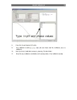
Page 30: ...Least Square Fit button 9 The calibration results φmax φmin dpH pH0 are shown and the calibration curve is displayed 10 Save your set of calibration values by pressing Transfer Data 11 Enter the new calibration constants and the temperature in the calbriation window ...

Page 31: ...lues to obtain maximum accuracy PLEASE NOTICE Exclude ambient light to minimize drift by photobleaching 7 2 Performance proof If you want to prove the performance during the past measurement please check the calibration buffers by inserting the sensor in the buffer solution pH 6 and pH 7 when you have finished your measurement If the device displays the correct pH values the sensor worked perfectl...

Page 32: ... other organic solvents The SMA fiber connector of the sensor can be cleaned only with lint free cloth Please clean the connector at least after having a sensor connected for more than 20 times 8 3 Service Balancing maintenance and repair work may only be carried out by the manufacturer PreSens Precision Sensing GmbH Josef Engert Strasse 11 D 93053 Regensburg Germany Phone 49 941 942 72 0 Fax 49 9...

Page 33: ...ts OPTICAL OUTPUT INPUT Optical connector SMA Channels 10 Wavelength 470 nm AC INPUT AC Range 220 V DIGITAL OUTPUT communication protocol serial interface RS232 38400 Baud Databits 8 Stoppbits 1 Parity none Handshake none instrument output on RJ11 4 4 plug Interface cable to PC RJ11 4 4 to DSub9 ...

Page 34: ... ENVIRONMENTAL CONDITIONS Operating temperature 0 to 50ºC Storage temperature 10 to 65ºC Relative humidity up to 95 OPERATION CONTROL LED at the front panel DIMENSIONS length 300 mm width 250 mm height 140 mm weight 3600 g ...

Page 35: ...The SMA connector is a high precision optical component Please keep it clean and dry Always use the rubber cap to close the output when not in use 9 2 Operation Notes Measurement To achieve the highest accuracy the pH 10 mini should be warmed up for 5min before starting the measurement Please see the details of measurement process described in pH 10 mini manual ...

Page 36: ...d where luminescence excitation or emission is measured at two wavelengths this scheme uses a couple of luminophores with different decay times and similar excitation spectra An analyte insensitive µs lifetime luminophore is combined with an analyte sensitive ns lifetime fluorophore and a method is presented how to convert fluorescence intensity into a phase shift Preferably the reference dyes dis...

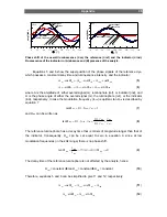
Page 37: ...luminophore ref or indicator ind and Φ is the phase angle of either the overall signal m the luminophore ref or the indicator ind respectively In case the modulation frequency fmod is optimal tan Φref is described by equation 7 1 f 2 tan ref mod ref Φ τ π 7 and Φind can be written as ref ind ref ind ind ind f τ τ τ π τ π τ π Φ 2 2 2 tan mod 8 The reference luminophore has a decay time that is orde...

Page 38: ...f ind ref ref m m m m m A A A A A A A Φ Φ Φ Φ Φ Φ Φ sin 1 cot sin cos cot sin cos 13 In this equation cotΦm reflects the referenced intensity of the fluorescence indicator A linear relation is obtained between cot Φm and the ratio of Aind Aref because the phase angle of Φref of the reference luminophore was assumed to be constant This method is referred to as Dual Lifetime Referencing DLR ...

Reviews: