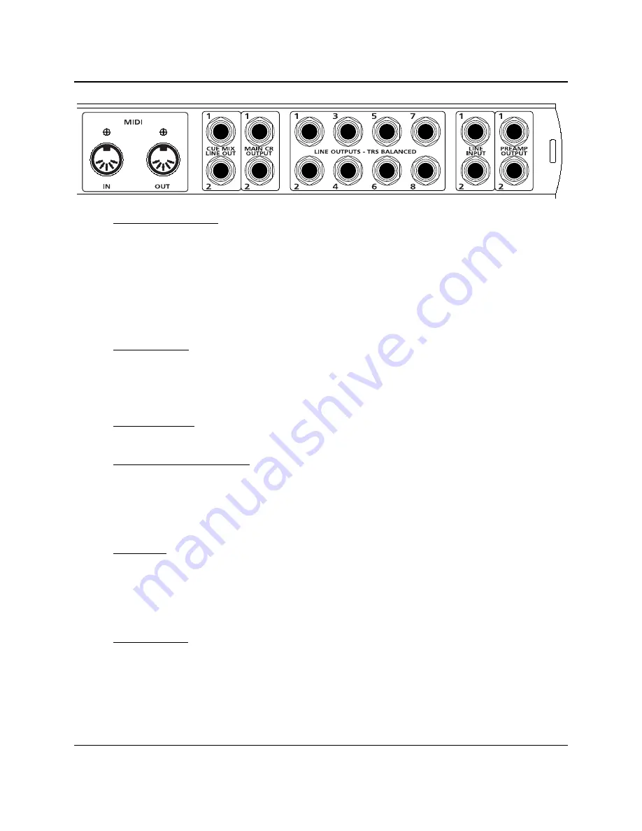
CONTROLS AND CONNECTIONS
24
|
PreSonus 2007
•
MIDI In and Out Ports.
MIDI stands for “Musical Instrument Digital Interface”. However, the MIDI
standard goes well beyond just instrumentation and sequencing. The MIDI inputs and outputs allow
connection and/or communication with external MIDI equipment. One function of this port is MIDI
programming. These can also be used for MMC (MIDI Machine Control) and MTC (MIDI Time Code).
NOTE:
MIDI is not audio
but is frequently used to trigger or control an audio source (such as a VST
plugin or synthesizer). When using MIDI, ensure your MIDI data is correctly sent and received by the
appropriate hardware or software instruments. You may also need to return those devices’ audio to the
FP10. Please consult the User’s Manual of your MIDI devices for help with MIDI setup and usage.
•
Main CR Output.
This is the output result of the FP10 Mixer knob. The output level of the Main CR
Outputs is controlled by the FP10 Main volume knob on the front of the unit.
NOTE: If the Mixer knob is turned fully counter-clockwise (left) to ‘Inputs (1-8)’, you will not be able
to hear the computer’s playback. Instead, you will only hear a mix of the analogue inputs.
•
Cue Mix Line Out.
These outputs are the same as the Main CR Output except do not have an associated
volume control knob and are not affected by the Main volume knob on the front of the FP10.
•
Line Outputs – TRS Balanced.
These are general purpose line-level outputs. Line Outputs 1 & 2 are
typically your computer’s audio playback. All eight Line Outputs can be accessed by your computer and
can be used for separate mixes, additional speakers, external effects processors, etc.
NOTE: As of firmware version 2, the FP10 acts as an eight channel preamplifier by routing the eight
analogue inputs directly to the eight Line Outputs when no sync source is present (Red Sync Light).
•
Line Inputs.
These are the line-level inputs for channels 1 & 2. Their gain structure is identical to the
¼” inputs for channels 3-8 and are typically used for signals not requiring preamplification (like
CD/MP3 players, effects processors, etc.) These inputs are normalled to the channel 1 & 2 preamp
outputs, so take precedence over the corresponding combination Mic/Instrument input on the front of
the FP10. (I.E., if a cable is plugged into channel one line input on the rear of the FP10, the channel
one Mic/Instrument input will be inactive until the cable is removed from line input one.)
•
Preamp Outputs.
These ¼” jacks are balanced outputs of the preamps on channels 1 & 2. They are
half-normalled to the line inputs 1 & 2, so plugging a cable into either of the preamp outputs does not
interrupt the signal flow from the preamp outputs to the line inputs (and to the ADC).
NOTE: The Preamp Outputs are typically used for patching in external signal processors such as
compressors, limiters, EQ’s, de-essers, etc. to the audio signals on channels 1 or 2. These Preamp
Outputs are not connected to the DAC (digital to analogue converters) in any way and so are only
capable of routing the input signals from channels 1 & 2. If you need to route recorded audio or input
from channels 3-8, you will need to use your recording software and one or more of the Line Outputs.
Summary of Contents for FP10 - SCHEMA 1
Page 4: ......


