53
7 Alarms and error handling
7.1 Faults and alarms
The Touchscreen software, the PRESS-display and the PRESS-control can generate error messages and alarms when
something is wrong with the system. The difference between an error and an alarm is the seriousness of the problem. An
error message is considered to be less serious than an alarm message. An alarm message is mainly about critical
problems in the expansion system. For example, a sensor malfunction or when the water level has exceeded the
maximum or minimum height. An error message is mainly about less critical errors in the system, or an early warning for
an alarm.
When a fault message or an alarm message occurs, the PRESS-control will always activate its collect alarm relay. This
relay is potential free. The collect alarm relay is used for connecting a warning signal to any type of device that notifies
the user. For example: the collect alarm signal can be send to the main computer or SCADA system to indicate that there
is a problem with the expansion system. The collect alarm relay reacts to all faults and alarms.
When an alarm message appears, the PRESS-control will also activate the boiler alarm relay. This relay is potential free.
The boiler alarm relay can be used to connect blocking signals to devices that have to stop in case of a critical problem in
the expansion system. For example: if the water level in the heat storage tank is higher than the setting ''lowering the
water level'' and ''maximum water level'', the water will press against the roof of the tank and may therefore not expand
further. With the boiler alarm relay, a signal can then be sent to the boiler to stop the heating of the water. This prevents
further expansion.
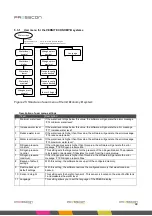
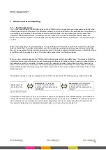
The faults and alarms can also be regarded to as two different alarm levels. The following image further clarifies this.
Alarm level: 0,
No malfunctions
Alarm level: 1,
A fault has
occurred. The collect alarm
activates and the display shows
“WARNING”.
Alarm level: 2,
An alarm has
occurred. The boiler alarm
activates and the display shows
“Alarm!”.
Figure 30. Alarm levels
The description of the alarm levels as shown above is based on the operation of the PRESS-display. The Touchscreen
handles the alarms in the same way as the PRESS-display but shows it to the user in a different way. Should an error or
alarm message occur, the component to which the message refers will turn red. By pressing the red component, the
Touchscreen displays the error and alarm information with an error code. See also chapter 4.2
Summary of Contents for HORNIT N2
Page 2: ...2...


