background image


63 

8


Maintenance and service 


8.1  Expansion system maintenance 

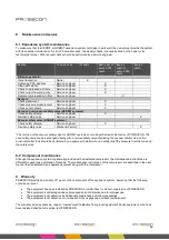
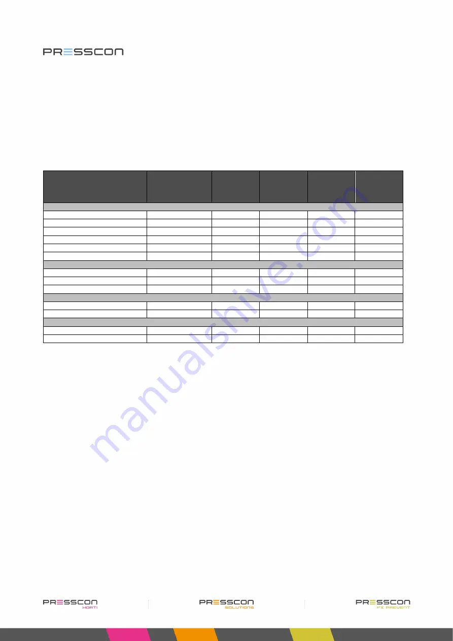
To make sure that the VERNIT or HORNIT expansion system continues to work well, the owner must provide the system 
with its essential maintenance. A part of the maintenance, the weekly checks, are usually done by the owner or its 
technical personnel. Other annual checks should be performed by a service engineer. 


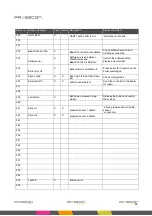
Activity 

To be done by 

Weekly 

Each year or 
every 2.000 
hours 

Every 2 
years or 
every 4.000 
hours 

Every 2 
years. 

Nitrogen generator 

Visual inspection 

Owner 


Tightening PSA spindles 

Service engineer 


Clean dirt catcher 

Service engineer 


Check compressed air filters 

Service engineer 


Check output flow and purity 

Service engineer 


Replace compressed air filters 

Service engineer 


Sensors 

Check water level 

Service engineer 


Check pressure measurement 

Service engineer 


Check sensor covers 

Service engineer 


Vacuum- overpressure safety valve (VERNIT systems) 

Check safety valve(s) 

Service engineer 


Revision safety valve 

Service engineer 


Vacuum safety valve (HORNIT systems)


Check safety valve(s) 

Service engineer 


Revision safety valve 

Mechanic/Factory* 


*The revision of the vacuum safety valve for HORNIT systems should be performed at the factory of PRESSCON. The 
used safety valve can be exchanged directly with a revised safety valve. Replacing the vacuum safety valve on the 
horizontal buffer tank should be performed by an approved installer who can safely relief the pressure from the tank and 
the safety valve. 


8.2  Compressor maintenance 

Although the expansion system is generally provided with a dedicated compressor, the maintenance instructions are 
different for each type and brand of machine. The maintenance instructions of the compressor are described in the user 
manual that is delivered as a separate document along with the compressor.       


9  Warranty 

PRESSCON provides a warranty of 1 year on the components of the expansion system, assuming that the following 
conditions are met: 


The equipment has been installed by PRESSCON or under direct or indirect supervision of PRESSCON.  


The equipment is undamaged and unprocessed and not defective due to improper use. 


The equipment is not defective by inadequate maintenance or other proceedings. 


The equipment is not defective or non-speech hit by negligence, accident or whatsoever.  
 

The warranty includes checking, repair or replacement if defective from proven equipment. Faulty equipment, which has 
been replaced shall become property of PRESSCON. 

Summary of Contents for HORNIT N2

Page 1: ...VERNIT HORNIT N2 i expansion systems User manual Type User manual Date 18 09 2019 Version Revision Version 4 2 Revision 00 Status Approved Company PRESSCON Location Honselersdijk...

Page 2: ...2...

Page 3: ...3 1 5 Protection against overpressure and vacuum with VERNIT systems 20 3 1 6 Protection against vacuum with HORNIT systems 21 3 1 7 Leak detection measurement SLDM or CLDM for VERNIT systems optiona...

Page 4: ...menu schematic for Touchscreen type ECONOMY A and ECONOMY DUO 44 4 4 Service menu 45 4 5 Factory menu 45 4 6 Standby 45 5 PRESS display 46 5 1 Buttons on the PRESS display 46 5 1 Menu structure and a...

Page 5: ...central heating system to expand and shrink when the water is heated up or cooled down During this process the pressure in the expansion chamber also changes The VERNIT HORNIT expansion system monitor...

Page 6: ...water level from becoming too low which leads to air in the heat supply spray tube and in the central heating network These are important features for maintaining the buffer tank and preserving the c...

Page 7: ...stem uses a separate pressure vessel in which the nitrogen is first stored before it is blown into the heat storage tank A panel The addition A indicates that the expansion system is equipped with the...

Page 8: ...rms The Touchscreen also performs these functions but offers a more visual overview of the system and more intuitive controls The Touchscreen can also be universally used for multiple types of nitroge...

Page 9: ...e work is conducted The safety valves on both the vertical and horizontal buffer tanks The safety valve on a vertical buffer tank can be depressurized by hand The pressure is not higher than 28 mBar T...

Page 10: ...ng on it 5 MACHINE WITH AUTOMATIC START Machine stops and starts automatically when it is operating normally Turn off the machine completely before working on it 11 ATTENTION Special situation occurs...

Page 11: ...mponents by giving an image of each device and by numbering the most important parts The compressor is not described because different brands and types can be applied and it is delivered with its own...

Page 12: ...12 2 2 Nitrogen generator type ECONOMY B N2 system N2i system Figure 3 N2 ECONOMY B system Figure 4 N2i ECONOMY B system 3 3 5 B 6 8 10 7 9 2 4 11 1 1 2 3 1 3 1 4 3 3 5 B 6 8 10 7 9 1 11 1 3 1 3 1...

Page 13: ...ogen generator type ECONOMY DUO N2 system N2i system Figure 5 N2 ECONOMY DUO system Figure 6 N2i ECONOMY DUO system 3 3 8 10 7 9 1 B 2 4 5 A 6 1 A 11 1A 2 1B 3 1 3 1 4 3 3 8 10 7 9 1 B 5 A 6 1 A 11 1B...

Page 14: ...n the display will turn green If the pressure then drops below 4 0 Bar the text on the display will turn red and a new start signal is generated 5 A Touchscreen Standard for ECONOMY A and ECONOMY DUO...

Page 15: ...mechanically operating valve plate with calibrated lead slices that relieves nitrogen at the maximum allowed pressure It is protected with an additional cover 2 Operating overpressure valve A mechani...

Page 16: ...ressure safety valve Legend Ref No Description Function 5 Tracing band Band that is heated when powered with electricity 6 Thermostat Thermostat that monitors the surrounding temperature at the sensor...

Page 17: ...lated holder with tubing that holds the pressure sensor The sensor holder functions as additional protection against heat and moisture It also allows the pressure sensor to be easily exchanged 5 Threa...

Page 18: ...f No Description Function 7 Tracing ribbon Ribbon that is heated when powered with electricity 8 Thermostat Thermostat that monitors the surrounding temperature at the sensor and activates the tracing...

Page 19: ...environment The remaining mix of oxygen and nitrogen has a purity of 99 0 vol N2 The nitrogen mix is fed to the vertical or horizontal buffer tank and the pressure of the nitrogen blanket or total sys...

Page 20: ...er tank measure the increased water level When the water has reached the minimum height in accordance with the settings of the Touch Screen or the PRESS display the water pump stops The water level re...

Page 21: ...t the water expands and the total system pressure increases When the pressure of the nitrogen blanket is at its maximum working pressure the nitrogen generator will activate a solenoid valve The nitro...

Page 22: ...ting Buffer press minimal a water leakage alarm message is generated Step 4 The Leak detection measurement also protects the buffer tank from being overfilled with water This will be indicated with an...

Page 23: ...24Vac for the check valve The 3 position switch then determines if these contacts react automatically or open permanent in the normally or close permanent in the normally By connecting the check valve...

Page 24: ...underside through which heated water is injected into the buffer tank The pressure sensor on the side of the buffer tank is always above the center of the injection pipe 6 Pressure sensor 5 6 0 1600...

Page 25: ...ure it with a 3rd pressure sensor at the bottom of the tank This pressure sensor can be used for setting up the leak detection measurement Since the leak detection measurement is an optional feature i...

Page 26: ...The pressure sensor on the side of the buffertank is always above the center of the injection pipe 6 Pressure sensor 3 0 600 mBar Electronic transmitter that measures the pressure of the nitrogen blan...

Page 27: ...e 13 Components on a single horizontal buffertank with a partition wall Figure 14 Components on a single horizontal buffertank with a separate expansion vessel Ref no Description Function 1 Vacuum saf...

Page 28: ...sor on the side of the buffertank is always above the center of the injection pipe 5 Separate expansion vessel Separate vessel in which the water from the buffertank can expand This component is part...

Page 29: ...which heated water is injected into the buffertank The pressure sensor on the side of the buffertank is always above the center of the injection pipe 5 Pressure sensor 3 0 1000 mBar 0 1600 mBar 0 2500...

Page 30: ...N2 i system overview PRESSCON Buffer tank Control PRESS control minimal Boiler Notification device Nitrogen generator Water pump Pressure Sensor 2 Pressure Sensor 1 CAN bus Analoguewater level Analogu...

Page 31: ...loguewater level Analogue nitrogen pressure External generator Alarm notifier Boiler on off Water inlet Water outlet Nitrogen inlet valve Valve control Nitrogen pressure Expansion tank Compressor Drai...

Page 32: ...2 Water inlet Water outlet Sensor offset 9 meter Nitrogen inlet valve 25 mBar Mechanical pressure release valve 20 mbar Nitrogen outlet valve Valve control Nitrogen pressure Hot water buffer tank 2 Co...

Page 33: ...Expansion tank Horizontal heat storage tank 1 Water pump Pressure Sensor 1 Vacuum safety valve Vacuum safety valve Nitrogen relief valve PRESSCON Buffer tank DUO Control PRESS control maximal Nitrogen...

Page 34: ...ce Service menu Factory Factory menu Press the button to view the current fault and alarm messages Press the button for more than 3 seconds to view the alarm log Pressing this button calls up the info...

Page 35: ...e of system the user has Press the icons to find out the status of this system Figure 20 VERNIT 2 0 30 0 N2 i DUO system overview Only when the VERNIT is installed 4 1 2 Main screen lay out HORNIT Fig...

Page 36: ...he status of the compressor is forwarded to the PressControl Compressor Description status The compressor supplies the compressed air to the system When it is colored white de compressor is working pr...

Page 37: ...sensor measures the value of the oxygen which remains after generation the nitrogen from the PSA generator The status of the oxygen sensor is forwarded to the PressControl Oxygen sensor Description s...

Page 38: ...When the valve turns green it means the valve is open 4 2 5 Overpressure safety relief The overpressure safety reliefs are on top of the tank These protection devices are only visible with VERNIT syst...

Page 39: ...n the tank is represented like this the tank has a water level failure When the tank is represented like this the tank has a system pressure failure Press the tank to go to the fault menu When the tan...

Page 40: ...epresented by the height of the blue part in the tank The range is calculated between the water level maximum and water level minimum settings This range is divided in 10 parts Next the current water...

Page 41: ...o the tank When the tank is represented like this the tank is functioning properly When the tank is represented like this the tank has a water level failure Press the tank to go to the fault menu When...

Page 42: ...epresented by the height of the blue part in the tank The range is calculated between the water level maximum and water level minimum settings This range is divided in 10 parts Next the current water...

Page 43: ...as a system pressure failure Press the tank to go to the fault menu When the tank is represented like this the tank has system pressure failure and water level failure Press the tank to go to the faul...

Page 44: ...5 Water level decrease 6 Water level maximum 7 Nitrogen pressure minimum 8 Nitrogen pressure nominal 9 Nitrogen pressure maximum 10 Buffer pressure minimum 11 Buffer pressure maximum 12 Standard stet...

Page 45: ...n of the PRESS control motherboard and the touchscreen This menu is meant for setting the nitrogen generator when tested in the factory The factory menu can be approached by pressing the factory butto...

Page 46: ...menu An access code is required Press and hold for 3 seconds to view the factory menu An access code is required Adjusting a setting in one of the menus In the user menu press and hold this button for...

Page 47: ...u The user menu contains all the basic settings for the expansion system In this menu the user can set values such as start values stop values alarm values for nitrogen blanket pressure total system p...

Page 48: ...he target value for the pressure of the nitrogen blanket The pressure is increased or decreased if it deviates too much from the nominal value 7 Nitrogen pressure maximum If the nitrogen pressure is h...

Page 49: ...T ECONOMY B Description of the service information screen Tekst Description 1 Tank pressure This screen shows which measured values are used to determine the pressure of the nitrogen blanket or the to...

Page 50: ...ler protection It indicates whether a signal from the Switch B button on the PCB of the PRESS control is being received and it indicates how many days the boiler protection has been switched off It al...

Page 51: ...the PRESS control motherboard and the PRESS display This menu is for setting up the nitrogen generator when it is tested at the factory The factory menu can be accessed by pressing the button for 3 se...

Page 52: ...or sensors and an analogue output signal with 4 20mA 6 1 Types of PRESS control Depending on the type of control cabinet there are also different types of PRESS control Printed circuit boards PCB s Th...

Page 53: ...the boiler alarm relay This relay is potential free The boiler alarm relay can be used to connect blocking signals to devices that have to stop in case of a critical problem in the expansion system F...

Page 54: ...e button with the designation SWITCH B is programmed to override the boiler alarm relay The button should be pressed and held for 3 seconds to activate the override The PRESS display will then give 2...

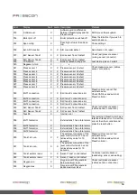
Page 55: ...ontrolled to long Problem with the automatic fill relief installation F13 WaterOut timeout X Water output controlled to long F14 Waterlevel min X X Water below minimum level Add water F15 Waterlevel m...

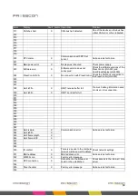
Page 56: ...nd external PressController F50 ElcT2 connection X X ELC tank Y connection error F51 SlcT1 connection X X SLC tank X connection error F52 SlcT2 connection X X SLC tank Y connection error F53 SLC Senso...

Page 57: ...k2 press sens X An external pressure sensor for the tank 2 control has an error F74 Buffer connect X The connection of the buffer pressure measurement has a timeout fault F75 BufferPress min X Buffer...

Page 58: ...PressControl JGA953 F25 F26 F27 F28 Uart rxFifo X UART receive buffer full Too much debug information send or noise on the connection F29 Uart txFifo X UART send buffer full F30 F31 F32 F33 F34 F35 F...

Page 59: ...cian F58 F59 F60 TCP Tx buffer X F61 F62 F63 TCP Rx buffer X F64 F65 F66 F67 Double devNr d X Double device number detected Check device number on the CAN bus F68 F69 F70 F71 F72 F73 F73 Display error...

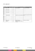
Page 60: ...irst time starting new cfg F10 F11 CAN bus halt CAN bus stop detected One of the devices on the bus had a fatal CAN error or has been restarted F12 x F13 x F14 Waterlevel min X X Water below minimum l...

Page 61: ...er F34 Boiler prot off X Boiler alarm is switched off Press button B to switch on the boiler alarm again F35 Span config X X Span high is lower than Span low Check configuration F36 External ADC X X A...

Page 62: ...operating for 14 days Make sure that a maintenance service has been carried out within two weeks Call service technician F68 Service expir No maintenance service carried out system will shut down Cal...

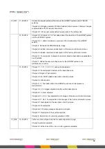
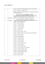
Page 63: ...evision of the vacuum safety valve for HORNIT systems should be performed at the factory of PRESSCON The used safety valve can be exchanged directly with a revised safety valve Replacing the vacuum sa...

Page 64: ...ents relating to goods to be delivered and or services within the Netherlands are applicable the general terms and conditions for the technology industry as last filed by the FME CWM with the court in...

Page 65: ...justed to TYPES instead of TYPE Chapter 2 5 Title adjusted to TYPES instead of TYPE Chapter 3 1 1 Step 1 about the compressor placed into a separate paragraph Grammar in text adjusted Chapter 4 1 the...

Page 66: ...HORNIT system to the maintenance overview 13 01 2016 Chapter 1 1 1 1 1 1 1 2 1 1 3 various texts adjusted Chapter 2 0 Text adjusted to better suit the described units Chapter 2 0 legend Text adjusted...

Page 67: ...troduction text of chapter Description of heat injection pipe also added Added paragraph for the leak detection measurement Adjusted size of function column in description table Chapter 3 2 2 added ch...

Page 68: ...1 Adjusted description of pressure sensor Chapter 3 2 1 Added legend with remark on components that PRESSCON does not install Chapter 3 2 2 Added legend with remark on components that PRESSCON does n...

Page 69: ...rammar under VERNIT 2 0 30 0 N2 i ECONOMY B Chapter 1 1 Grammar adjusted Chapter 1 1 1 Grammar adjusted Chapter 1 1 2 Grammar adjusted Chapter 1 1 3 Grammar adjusted Chapter 1 2 Grammar adjusted Chapt...

Page 70: ...uring range of sensors in legend 19 04 2017 Chapter 7 1 Grammar adjusted in text and in table about maintenance Chapter 9 Adjusted description of quality management system 3 5_R00 27 10 2017 2 1 Image...

Page 71: ...r working with a product of PRESSCON Its aim is to maintain and possibly improve the quality of its products If additional information or support is requested then PRESSCON can be consulted through th...

Reviews: