background image

128-9480

1 of 16

Page 1

Model APSRS1Z

Installation Manual

PATENTED:  www.voxxintl.com/company/patents

Table Of Contents:

Before You Begin 

Page 2

Wire Harness Quick View 

Page2 & 3

Installation Of The Major Components 

Page 4

Wiring The 6 Pin Main Power Harness 

Page 5

3 Wire Negative Switched Door Lock Circuits 

Page 6 & 7

Wiring The 10 Pin Input/Output Harness 

Page 7 - 9

4 Pin Main Harness 

Page 9

5 Wire Antenna Receiver Connector 

Page 9

Tachometer Rate Programming 

Page 10 & 12

Programming Bank 1 (Transmitter) 

Page 10

Programming Bank 2 (Alarm Features) 

Page 10 & 11

Programming Bank 3 (Remote Start) 

Page 12 & 13

Diagnostics 

Page 14

4 Pin Data Bus Port 

Page 14

Completing The Installation 

Page 15

Circuit Wiring Diagram 

Page 16

FCC COMPLIANCE

 This device complies with part 15 of the FCC Rules. Operation is subject to the following two conditions: 

 (1) This device may not cause harmful interference, and 

 (2) this device must accept any interference received, including interference that may cause undesired operation.

 This equipment has been tested and found to comply with the limits for a Class B digital device, pursuant to part 15 of the FCC Rules. These 

limits are designed to provide reasonable protection against harmful interference in a residential installation. This equipment generates, uses 

and can radiate radio frequency energy and, if not installed and used in accordance with the instructions, may cause harmful interference to 

radio communications. However, there is no guarantee that interference will not occur in a particular installation. If this equipment does cause 

harmful interference to radio or television reception, which can be determined by turning the equipment off and on, the user is encouraged to 

try to correct the interference by one or more of the following measures:

 —Reorient or relocate the receiving antenna.

 —Increase the separation between the equipment and receiver.

 —Connect the equipment into an outlet on a circuit different from that to which the receiver is connected.

 —Consult the dealer or an experienced radio/TV technician for help.

 Warning!

 Changes or modifications made to this equipment not expressly approved by the part responsible for compliance could void the use’s author

-

ity to operate the equipment

 NOTE: The manufacturer is not responsible for any radio or TV interference caused by unauthorized modifications to this 

 equipment. Such modifications could void the user’s authority to operate the equipment.      

Summary of Contents for 1124316

Page 1: ...the FCC Rules These limits are designed to provide reasonable protection against harmful interference in a residential installation This equipment generates uses and can radiate radio frequency energ...

Page 2: ...as it may prevent proper operation of the vehicle Tape or loom wires under the hood and dash for protection as well appearance Use grommets when routing wires through metal surfaces to prevent chafin...

Page 3: ...ge Tachometer Input 2 Empty Cavity NA 3 Black Blue Pulse Before Start 4 Black LT Green Pulse After Start 5 LT Blue Ground While Running Output 6 Green Yellow Glow Plug Input 7 Brown Stop Input Brake S...

Page 4: ...toward the control module using caution not to pinch the cable as this will cause poor or no RF reception to the control module Connect the 5 pin cable to the mating connector of control module HOOD P...

Page 5: ...on switch This wire will show 12 Volts when the ignition switch is turned to the ACCESSORY or ON and RUN positions and will show 0 Volts when the key is turned to the OFF and START or CRANK positions...

Page 6: ...icle you are working on and wire according to the diagrams shown 3 Wire Negative Switched Door Lock Circuits In this application the Black Blue provides a negative pulse before starting While running...

Page 7: ...are working on as well as how to use them 1 Green Orange Wire Tachometer Input Signal This wire will continually monitor the engine s tach rate while the unit is under power of the Remote Start module...

Page 8: ...g this wire to the glow plug 12 Volt wire when the remote start unit activates the ignition one output the glow plug output also activates The remote start sees the Green Yellow with positive voltage...

Page 9: ...is wire is also referred to as the ECM wake up wire in some Chrysler vehicles NOTE The outputs above are low current outputs and must be used with a relay if the circuit s requirement is more than 250...

Page 10: ...r connection or a poor tach source the parking lights will not flash To correct this situation locate and connect the Green Orange Wire to the proper tach signal and then repeat the tach learn routine...

Page 11: ...ection 1 Chirp 2 Chirps 3 Chirps 4 Chirps 5 Chirps 6 Chirps 1st DoorL UL 1S 1S 3 5 Sec 500mS L Dbl U L Dbl L 500mS UL Dbl L Dbl UL 500mS 350mS ul 2nd Accy Lock Not Available 3rd Accy UL Not Available...

Page 12: ...shbutton switch five times to advance to features 5 Input Check then use the transmitter button to select three chirps DBI Tach 6 To exit the programming mode turn the ignition key off The program mod...

Page 13: ...Diesel 10 Diesel 15 Diesel 20 12th Transponder O P Not Available 13th Temp Start Not Available 14th Crank Averaging Averaging Preset Time Note When averaging the engine must be started 4 times with t...

Page 14: ...Flashes High tach signal RPM 7 Flashes Tach signal has not been learned 8 Flashes Negative inhibit wire activation 4 PIN DATA BUS PORT DBI Port The 4 pin port located on the side of this module is fo...

Page 15: ...ome in contact with under the dash board or in the engine compartment areas CAUTION Particularly avoid the area around the steering shaft and column as wires can wrap around these mechanisms and impai...

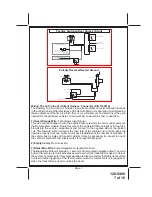
Page 16: ...ing Light Relay Input Wire Side View Of Connector 1 Blue Ign 1 2 Red White 12VDC Relays Ign 1 Ign 2 3 Green Ign 2 4 Purple Accessory 5 Red 12VDC Relays ACC Start 6 Yellow Starter 1 2 3 4 5 6 1 Green O...

Reviews: