background image

128-9310

3of 30

3

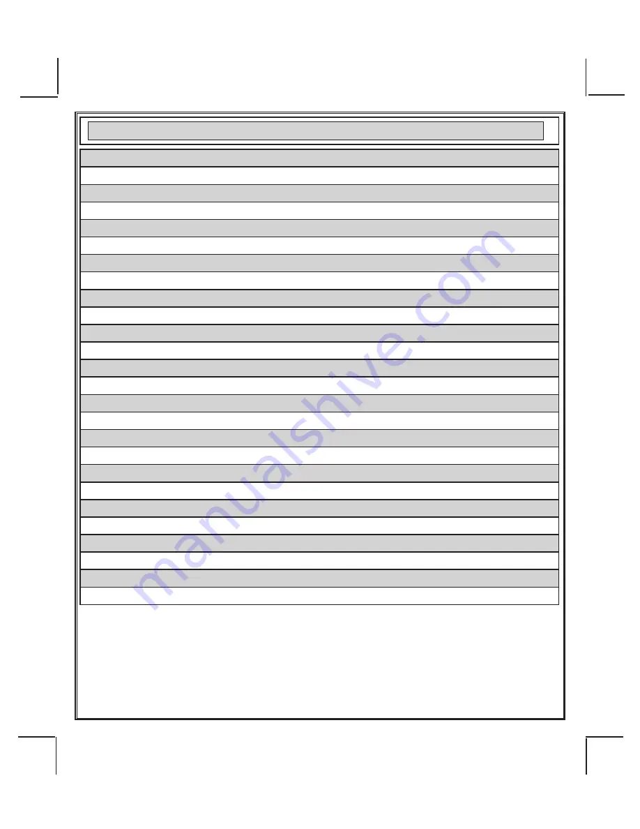
26 Pin Main Wiring Harness #1124302

1   Green/White 

Dome Light Output (-)

2   LT. Blue 

Ground While Running Output (-)

3   Black/White 

Horn Output (-)

4   Purple 

(+) Door Trigger input

5   Brown/Black 

(+) Inhibit/Shutdown To Brake Switch

6   DK. Blue/Black 

External Remote Start Trigger Input (-)

7   Orange/Black 

(-) Parking Brake Input

8   Green/Yellow 

Glow Plug Input

9   Brown 

(-) Door Trigger Input

10 Green/Orange 

Tachometer Input

11 DK Green 

(-) Instant Trigger Input

12 NC 

No Connection, Empty Cavity

13 LT. Green 

(-) Trigger Input

14 DK. Blue 

Channel 3 Trunk Release Output (-)

15 Green/Black 

Channel 4 Output (-)

16 DK.Blue/Red 

Channel 7 Output (-)

17 Black/LT.Green 

Pulse After Start Output  (-)

18 Black/Blue 

Pulse Before Start Output  (-)

19 Black/Red 

Pulse After Shut Down Output (-)

20 Black/Yellow 

Pulse During Crank Output (-)

21 LT. Blue/Black 

Channel 6 Output (-)

22 LT.Blue/Green 

Channel 5 Output (-)

23 Gray/Black 

(-) Inhibit/Shutdown To Hood Switch

24 Orange 

Start Inhibit Relay Control (-)

25 White/Blue 

(-) Headlight Activation Output

26 Orange/White 

N.O Start Inhibit Relay Control (-)

Summary of Contents for APS-997LORA

Page 1: ...k Sensor Harness Page 19 Time Start Programming Information Page 19 Temperture Start Programming Information Page 19 DBI Port Information Page 19 Diesel Engine Setting Information Page 19 Diagnostics Access Information Page 20 Engine Monitoring Selections Voltage Tach DBI Hybrid Page 20 Tach Programming Page 20 28 Testing Your Installation Hood Pin Safety Page 21 Manual Override Safety Testing and...

Page 2: ...plies with part 15 of the FCC Rules Operation is subject to the following two conditions 1 This device may not cause harmful interference and 2 this device must accept any interference received including interference that may cause undesired operation This equipment has been tested and found to comply with the limits for a Class B digital device pursuant to part 15 of the FCC Rules These limits ar...

Page 3: ... DK Green Instant Trigger Input 12 NC No Connection Empty Cavity 13 LT Green Trigger Input 14 DK Blue Channel 3 Trunk Release Output 15 Green Black Channel 4 Output 16 DK Blue Red Channel 7 Output 17 Black LT Green Pulse After Start Output 18 Black Blue Pulse Before Start Output 19 Black Red Pulse After Shut Down Output 20 Black Yellow Pulse During Crank Output 21 LT Blue Black Channel 6 Output 22...

Page 4: ... Pink Ignition 3 Common Contact 5 Purple Accessory 6 Red Battery 2 12V 7 Yellow Starter Output 8 Red Black Ignition 3 Normally Open Contact 1 Black Chassis Ground 2 White Red Parking Light Relay Input 3 White Black Siren Output 4 White Parking Light Relay Output 1 Red Door Lock Output 2 Green Door Unlock Output 3 Red Black 2nd Door Unlock Output 1 Blue Predetect 2 Green Full Trigger 3 Black Chassi...

Page 5: ...128 9310 5of 30 5 6 Pin Antenna Harness 1124293 1 Red 5 VDC 2 Green RX 3 Black Ground 4 Grey Valet Enable 5 Blue LED Cathode 6 Blue TX TRX17LORA 1181259 ...

Page 6: ...o the input wire activating the alarm In addition the hood switch is required for the safety shut down of the remote start unit If the vehicle is being worked on this hood switch prevents the remote start activation even if the RF command to start is issued This switch must be installed in all applications Failure to do so may result in personal injury or property damage PUSH BUTTONPROGRAM SWITCH ...

Page 7: ...it as well as the ignition 1 and ignition 2 relays 3 GREEN Wire Ignition 2 Output Connect this wire to the ignition 2 wire from the ignition switch This wire will show 12 volts when the ignition key is turned to the ON or RUN position and is some cases the START or CRANK position This wire will show 0 volts when the key is turned to the OFF and ACCESSORY positions NOTE See programming information ...

Page 8: ...itch is turned to the start crank position only This wire will have 0 volts in all other ignition switch positions NOTE This wire must be connected to the vehicle side of the starter cut relay when used For the electrical neutral switch configuration this connection must be made between the starter inhibit relay when used and the neutral safety switch as shown in the following diagram Failure to c...

Page 9: ... sensor s operation until the Remote Start unit shuts off B Additional Ignition Output Some vehicle s may require more than three ignition outputs to start and keep the vehicle s engine running If this is the case connect the Light Blue wire to terminal 86 of an external relay Connect terminal 85 to a fused 12 volt source Dependent on the vehicle s requirement connect terminal 30 to a fused 12 vol...

Page 10: ...le uses a 12 VDC horn switch then connect the black w white trace wire to terminal 86 of a 30Amp automotive relay and connect relay terminal 85 to a fused 12 VDC battery source Connect relay terminal 87 to the vehicle s horn switch output and connect relay terminal 30 to a fused 12 VDC battery source 4 Purple Wire Door Trigger Input If the vehicle s door courtesy light switches 12 volts when the d...

Page 11: ...e glow plug output also activates The remote start sees the green yellow with positive voltage and waits for this to go inactive drop to 0 volts before activating the starter motor If this wire is not used or you have difficulty access ing the glow plug preheat circuit you may elect to utilize the Diesel timed output as specified in Remote Start feature selection Bank 3 Feature 12 NOTE If green ye...

Page 12: ... mA switched output whenever channel four of the receiver is accessed Pressing the pre programmed transmitter button s will provide a 1 second pulse to channel four This is a low current output and must be connected to a relay to supply power to the device you intend to control Connect Green w Black Trace wire to terminal 86 of a 30 amp automotive relay Connect terminal 85 of the relay to a fused ...

Page 13: ...t is selectable and can function as described in feature selection of bank 3 feature 22 20 Black w Yellow trace Wire Ground Output During Start Crank The Black w Yellow Trace wire will provide a 300 mA ground output while the starter output of the remote start unit is active This output can be used to activate the Crank Low Bulb Test wire found in some GM vehicles This wire is also referred to as ...

Page 14: ...he relay provided Connect terminal 85 red wire of the relay to an ignition wire in the vehicle that is 12 volts when the ignition switch is turned to the on and start positions and off when the key is off Locate and cut the low current start solenoid wire found at the vehicles ignition switch harness This wire will have 12 volts when the ignition key is moved to the start crank position and will h...

Page 15: ... the starting circuit of the vehicle 4 Pin Additional Harness Parking Light Flasher I O Siren Ground Part 1284301 1 Black Chassis Ground Connect the Black wire to a known vehicle ground source or to a solid clean metal part of the chassis Be certain to remove any paint or grease and secure this wire with a self tapping screw and ring terminal 2 White w Red trace Wire Parking Light Relay Input Wire...

Page 16: ...ol the drivers door unlock relay and the Red Black will be used to control the unlocking of all other doors 3 Wire Ground Switched Door Lock Circuits In this application the Red wire of the door lock harness provides a ground pulse during the arming se quence or pulsed ground lock output Connect the Red wire to the low current ground signal wire from the factory door lock switch to the factory doo...

Page 17: ...ctory Switches 12 Volts Connect to Fused 12 Volt Source If Factory switches Ground Connect To Ground 87a 87 30 86 85 Fused 12 Volt Source Factory Unlock Relay 3 Wire Positive Switched Door Locks For three wire positive door lock circuits you will have to invert the output of the door lock wires with relays or with the DLVI Door Lock Voltage Inverter The DLVI converts a negative pulse to a 1A posit...

Page 18: ...al components which may include relays fixed resistor a door lock interface or a data module You can search the vehicle www avxtech1 com Flash It com for vehcile specific information or contact our tech service line or web site for additional information Additional Harnesses And Connectors For The System 4 Pin Upgrade Telematic Module Connector Port Red 5 Volts Black Ground White Data TX Yellow Da...

Page 19: ...start timer within 10 seconds of turning off the ignition switch activate the RF command to start 2 times Press the start button four times The lights will flash and the siren will chirp 4 times Indicating timed interval mode has been initiated The vehicle will automatically start every 2 or 4 hours as programmed To cancel the timed start mode start the vehicle either by RF or by the ignition key ...

Page 20: ...dule and have determined that a tach signal is available for the vehicle you are connecting to The unit will look at the DBI data port for the tach signal If the vehicle fails to start or the unit flashes 7 times recheck the DBI manual to insure that tach is available for your vehicle If not the tach connection wire Green Orange must be used 4 HYBRID SETTING Selecting this setting in the option me...

Page 21: ... Start Unit regardless of the RF transmitter operation To Enter The Remote Start Override Mode 1 With the system disarmed unlocked and the ignition switch off Press and Hold the pushbutton switch located on the receiver unit on 2 Turn the ignition switch on off on off on off 3 The LED begins to flash two short flashes followed by one long flashes and continues this pattern until returned to normal...

Page 22: ... BROWN BLACK NEUTRAL SAFETY WIRE TEMPORARILY DISCONNECTED IN STEP 3 MECHANICAL NEUTRAL SAFETY SWITCH CONSIDERATIONS Mechanical neutral safety switch configurations differ slightly in that they do not offer the same level of safety when installing a remote start device Often when the ignition switch is turned off while the gear selector is in any position other than park or neutral the mechanical f...

Page 23: ...METHOD 1 87a 87 30 85 86 To Fused 12 Volt Battery Source Ignition Key In Sense Wire Closes With Key In Cylinder 1N4002 Diode 1N4002 Diode Connect To Negative Remote Start Safety Shut Down Wire Drivers Door Pin Switch Key In Chime Module To Hood Pin Switch Safety Shut Down To connect to the key in sensor as shown in method 1 1 Locate the control wire that connects the drivers door pin switch to the...

Page 24: ...in switch is also used for an alarm trigger input be certain to use the dual diode set up shown earlier in this manual AFTER THE CONNECTION OF THE NEUTRAL START SAFETY WIRE AS INDICATED IN ANY OF THE PREVIOUS ALTERNATE CONFIGURATIONS THIS CIRCUIT MUST BE TESTED FOR PROPER OPERATION Retest by following the steps outlined in the NEUTRAL START SAFETY TEST section of the manual DOME DELAY LEARN FEATUR...

Page 25: ...the adjustment screw counter clockwise COMPLETING THE INSTALLATION After you have confirmed the operation of the Remote Start unit and tested all the safety features of the system 1 Mount the control module up and behind the dash securing it in place with cable ties or screws Be certain that the chosen mounting location will not inhibit any of the controls of the vehicle 2 Securely harness and tie...

Page 26: ... 2 etc then use the lock button of the transmitter to select the feature setting Example to set passive arming 1 Turn the ignition key to the on position 2 Press and release the valet programming switch 3 times Siren Chirps 3 Turn the ignition key off then on 1Siren chirps 2 times 4 Press the pushbutton switch six times to advance to features 6 Pass Act Arm then use the lock button of the transmit...

Page 27: ...irps 3 Chirps 4 Chirps 5 Chirps 6 Chirps 1st DoorL UL 500 mS 3 5 Sec 500mS L Dbl U L Dbl L 500mS UL Dbl L Dbl UL 500mS 350mS ul 2nd Accy Lock Auto Lock On Auto Lock Off 3rd Accy UL Auto UL Dr Auto UL All Auto UL Off 4th Headlights On Arm On Disarm On Both Off 5th Passive Locks Passive Active 6th Pass Act Arm Passive Arm Active Arm 7th Siren Horn Siren Horn Siren Only Horn Only 8th Horn Chirp 10mS ...

Page 28: ...s 5 Press the pushbutton switch five times to advance to features 5 Input Check then use the lock button of the transmitter to select three chirps DBI Tach 6 To exit the programming mode turn the ignition key off more than 6 seconds Siren sounds a short chirp followed by a long Chirp TACH RATE PROGRAMMING 1 Turn the ignition key to the On position 2 Press and release the valet program push button ...

Page 29: ...Time Note When averaging the engine must be started 4 times with the key to be effective 15th R S Shock Shunt Unit Clear Shunt R S Cycle Shunt From Tx 16th Turbo Select Off 3 Mins 5 Mins 10 Mins 17th One or Two Press Start Two Press One Press 18th Door Lock Control No Change Unlock Before Unlock Before Lock After Start Lock After Start Start 19th Alt O P Before Start Single Pulse As Feat 1 Bank 2 ...

Page 30: ...k LT Green Pulse After Start Output Gray Black Inhibit Shut Down From Hood Switch Brown Black Inhibit Shut Down From Brake Switch Purple Door Trigger Input Black White Horn Output Brown Door Trigger Input Green Orange Tach Input Orange Black Parking Brake Input Green Yellow Glow Plug Input Dark Blue Channel 3 Output Trunk LT Blue Green Channel 5 Output Green Black Channel 4 Output DK Blue Red Chan...

Reviews: