background image

Installation and Reference Guide

2020 Voxx Electronics Corpora�on. All rights reserved. 

APS57TM_RevD_07/20

Wire Harness Colors and Functions 


 2 

Power Connector

 3 

No�fica�on Connector

 4 

Input / Output Connector

External Components

 6 

RF Antenna Kit

 6 

Data Bus Interface (DBI)

 6 

Telema�cs

 6 

Weblink Programming


Setup Options


Remote Programming

 8 

Keyless Control

 10 

Remote Start Control

14 

System Operation


14


Remote Opera�on 

APS57TM  

Vehicle Remote Start / Keyless System

15 

System Programming


15 

Programming Mode Entry / Exit

 16 

Feature Bank Op�ons


17 

Data Port Protocol


17 

Tach Func�on


17 

Alarm Override

 18 

Silent Lock and Unlock

 18 

User Selectable LED

18 

System Diagnostics

 18 

Troubleshoo�ng Remote Start

19 

Wiring Diagrams

 19 

Door Lock Connec�ons


 22 

Full System Connec�ons

Thank you for trus�ng Pres�ge products! 

If you are a consumer,

 please note:

Professional installation is strongly recommended.


This manual assumes the installer has adequate knowledge of the following exper�se. Therefore, it does not 

cover these topics in detail:


• 

12-volt electronics


• 

Testing and verifying circuits


• 

Making safe and lasting wiring connections


• 

Factory ignition, power, lighting, data bus and sensing systems


• 

Factory systems and components to avoid


• 

Safe wire routing, circuit protection and product placement


• 

Access to vehicle-specific technical information

In addi�on, this manual assumes the installer has the 

proper tools, skill and facilities

 to perform a professional installa�on. 

Performing an improper installation could result in damage to the vehicle or its components, improper system function, 

unsafe vehicle operation or physical injury. 

Such instances would not be covered by the vehicle manufacturer's warranty, 

nor by Voxx Electronics, Inc. 

Detailed Descriptions

Quick Reference

Summary of Contents for APS57TM

Page 1: ...for trus ng Pres ge products If you are a consumer please note Professional installation is strongly recommended This manual assumes the installer has adequate knowledge of the following exper se The...

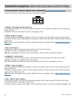
Page 2: ...ring engine crank Note This wire can be programmed to perform a different func on by changing its op ons Refer to Bank 3 Feature 7 on page 10 4 RED WHITE 12 Volt Input The RED WHITE wire connects to t...

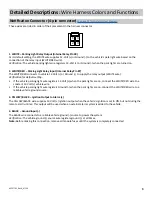
Page 3: ...e vehicle ground source 1 WHITE Parking Light Relay Output Internal Relay Pin 30 At its default setting the WHITE wire supplies 12 Volt or Ground to the vehicle s park light wire based on the connec o...

Page 4: ...erent func on by changing its op ons Refer to Bank 3 Feature 19 on page 10 7 BLACK LIGHT GREEN Factory Arm Output At its default setting the BLACK GREEN wire supplies a Ground pulse when the system is...

Page 5: ...t to the vehicle s Diesel Glow Plug detec on wire Verification This wire will register as 12 Volt while the Diesel Wait to Start Light is illuminated Detailed Descriptions Wire Harness Colors and Func...

Page 6: ...d and controlled through the data bus Please refer to the D2D Data to Data func on list available per vehicle at www FlashLogic com Telematics Interface The 4 pin Telema cs port enables a connected in...

Page 7: ...ols will delete the oldest programmed remote control Deleting All Remotes 1 Perform steps 1 3 above 2 Press and hold the valet bu on for ve 5 seconds 3 The system will sound one 1 long beep This indic...

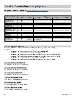
Page 8: ...Accessory Activated Unlock This Feature is not available on this model Feature 4 Exterior Illumination This Feature is not available on this model 1 Chirp 2 Chirp 3 Chirp 4 Chirp 5 Chirp 6 Chirp 1 Loc...

Page 9: ...beeps on or off when arming and disarming the system Setting Choices Option 1 Pressing Lock or Unlock at any me will perform the func on with audible beeps Option 2 Pressing Lock or Unlock for 1 5sec...

Page 10: ...GWR Igni on Accessory 21 Factory Arm Output After Start GWR Igni on Accessory Start 22 Pulse A er Shutdown After Shutdown GWR Igni on Accessory Start 23 Addi onal Unlock Pulse No Pulse IGN ACC GWR IGN...

Page 11: ...Start Sensing Voltage Level Func on Set the sensitivity of voltage variance measurement to determine if the vehicle has started when Feature 5 is set to option 2 Voltage Setting Choices Option 1 High...

Page 12: ...e is not available on this model Feature 16 Turbo Timer Setting This Feature is not available on this model Feature 17 Remote Start Activation Func on Set remote start to activate with one two or thre...

Page 13: ...on Set the functionality of the programmable output Setting Choices Option 1 Pulse During Crank Option 2 GWR Remote Start Status Output Option 3 Igni on Timing Option 4 Accessory Timing Feature 21 Fa...

Page 14: ...ss 1x Unlock Hold 3 Seconds Panic ON OFF Press 2x Start Programable Hold 3 Seconds Trunk Release Detailed Descriptions System Opera on Remote Control Operation This system includes two 2 remote contro...

Page 15: ...ocedure 1 Turn the igni on ON 2 Press and release the valet bu on three 3 mes 3 The system will beep 1 one me indica ng you have accessed Bank 1 4 Each cycle of the Igni on OFF ON will advance to the...

Page 16: ...2 Pulse A er Shutdown After Shutdown GWR Igni on Accessory Start 23 Addi onal Unlock Pulse No Pulse IGN ACC GWR IGN ACC GWR PASD Features Feature Bank 3 Op ons Quick Reference System Programming Bank...

Page 17: ...the Carlink App The vehicle s parking lights will flash seven 7 mes to indicate the tach signal has been learned If the parking lights do not flash locate another tach source and repeat steps 1 4 abo...

Page 18: ...rogram the Pres ge system to Lock and Unlock without no ca on beeps 1 Turn the igni on ON then OFF 2 Press and release the valet bu on three 3 mes The system will respond with one 1 beep for ON or two...

Page 19: ...re ac vated Negative Trigger Door Locks Verification The vehicle wires register Ground when the Lock and Unlock switches are ac vated Lock Unlock Vehicle Door Lock Control Relays RED Lock Output GREEN...

Page 20: ...itive Multiplex Door Locks Relays required Verification The vehicle wire registers variable 12V values when the Lock and Unlock switches are ac vated Please consult the vehicle speci c wire and loca o...

Page 21: ...d Aftermarket Actuators Relays and door lock actuators required Lock Unlock 87 87a 86 85 30 87 87a 86 85 30 Fused 12 Volt Battery Souce Fused 12 Volt Battery Souce RED Lock Output Green Unlock Output...

Page 22: ...V 3 Blue Data TX 2 Black Ground 1 White Data RX CarLink This Harness is included with the FLCART For Wire Informa on and Diagram Please Refer to Vehicle Speci c FlashLogic Install Guide Visit www Flas...

Reviews: