background image

APS901TM_R

e

vB_12/20

22

 Quick R

efer

ence: 

Wiring Diagr

ams

14

Green/Orange

Tach Input

13

Black/Yellow

Pulse During Crank Output (-)

12

Green/Yellow

Glow Plug Input (+)

11

Black/Red

Pulse A

er Shutdown Output (-)

10

Empty

Empty

9

Black/Blue

Factory Disarm Output (-)

8

Brown/Black

Brake Input (+)

7

Black/Lt. Green

Factory Arm Output (-)

6

Dk. Blue/Black

External Ac

va

on Input (-)

5

Lt. Blue

Remote Start Status Output (-)

4

Green

Unlock Output (-)

3

Gray/Black

Hood Input (-)

2

Empty

Empty

1

Black/White

Horn Output (-)

1

4

 P

in

 M

a

in

 I

n

p

u

t/

O

u

tp

u

t

1

2

3

4

V

OX

X

FLCART Dock

1

Yellow

Starter Output (+)

2

Green

Igni

on 2 Output (+)

3

Red

Ba

ery 12V Input (+)

4

Red/White

Ba

ery 12V Input (+)

5

Purple

Accessory Output (+)

6

Blue

Igni

on Input / Output (+)

6

 P

in

 R

S

 H

a

rn

e

ss

P

P

1

White

Parking Light (30) Output

2

White/Red

Parking Light (87) Input

3

Yellow/Black

Igni

on Output For Alarm (+)

4

Black

Ground Input (-)

4

 P

in

 L

igh

t

P

Replacement Part #4120463

Replacement Part #4120467

1

3

5

2

4

6

1

3

2

4

Replacement Part #4120465

Replacement Part #4120466

Accessory Sold Seperatly

Accessory Sold Seperatly

1

2

3

4

19

17

15

13

11

9

7

5

3

1

2

4

6

8

10

12

14

16

18

20

1

2

3

4

1

2

3

5

7

9

11

13

4

6

8

10

12

14

4

Red

Ba

ery 12V (+)

3

Blue 

Data TX

2

Black 

Ground (-)

1

White

Data RX

D

B

I

1

White

Data RX

2

Black 

Ground (-)

3

Blue 

Data TX

4

Red

Ba

ery 12V (+)

C

a

rL

in

k

This Harness is included with the FLCART.

For Wire Informa�on and Diagram Please Refer to Vehicle Specific 

FlashLogic Install Guide.

Visit www.FlashLogic.com for More Informa�on.

1

2

3

4

5

6

1

Pink

Ba

ery 12V (+)

2

Green

Data RX

3

Black

Ground (-)

4

Red

Valet Switch

5

Blue

LED (-)

6

Empty

Empty

A

n

te

n

n

a

Accessory Sold Seperatly

Replacement Part #4361008

4

Red

Ba

ery 12V (+)

3

Black

Ground (-)

2

White

Data RX

1

Blue 

Data TX

W

e

b

Li

n

k

181BPR

181BPR

4180070

Summary of Contents for APS901TM

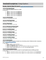
Page 1: ...r trus ng Pres ge products If you are a consumer please note Professional installation is strongly recommended This manual assumes the installer has adequate knowledge of the following exper se Theref...

Page 2: ...ring engine crank Note This wire can be programmed to perform a different func on by changing its op ons Refer to Bank 3 Feature 7 on page 10 4 RED WHITE 12 Volt Input The RED WHITE wire connects to t...

Page 3: ...le vehicle ground source 1 WHITE Parking Light Relay Output Internal Relay Pin 30 At its default setting the WHITE wire supplies 12 Volt or Ground to the vehicle s park light wire based on the connec...

Page 4: ...d if the driver door key cylinder is turned to the unlock posi on Note This wire can be programmed to perform a different func on by changing its op ons Refer to Bank 3 Feature 19 on page 10 7 BLACK L...

Page 5: ...as the RPM increases this is the proper tach wire 12 GREEN YELLOW Diesel Glow Plug Input The GREEN YELLOW wire connect to the vehicle s Diesel Glow Plug detec on wire Verification This wire will regis...

Page 6: ...stalla on me as many features that normally require individual connec on can be accessed and controlled through the data bus Please refer to the D2D Data to Data func on list available per vehicle at...

Page 7: ...memory Addi onal programmed remote controls will delete the oldest programmed remote control Deleting All Remotes 1 Perform steps 1 3 above 2 Press and hold the Valet bu on for ve 5 seconds 3 The syst...

Page 8: ...lock output timing and functionality for specific vehicle lock types Setting Choices Option 1 Lock and Unlock outputs will pulse for 500 milliseconds Option 2 Lock and Unlock outputs will pulse for 3...

Page 9: ...this model Feature 14 19 AUX Ch 5 Output This Feature is not available on this model Feature 15 19 AUX Ch 6 Output This Feature is not available on this model Feature 16 19 AUX Ch 7 Output This Featur...

Page 10: ...rank During Crank GWR Igni on Accessory 21 Factory Arm Output After Start GWR Igni on Accessory Start 22 Pulse A er Shutdown After Shutdown GWR Igni on Accessory Start 23 Addi onal Unlock Pulse NA Fea...

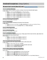
Page 11: ...Start Sensing Voltage Level Func on Set the sensitivity of voltage variance measurement to determine if the vehicle has started when Feature 5 is set to option 2 Voltage Setting Choices Option 1 High...

Page 12: ...d set door lock outputs to function before or after remote start Setting Choices Option 1 Remote Start Lock Control is inactive Option 2 Doors will unlock before remote start lock after remote start O...

Page 13: ...t Option 3 Igni on Timing Option 4 Accessory Timing Feature 21 Factory Arm Output Function BLACK LIGHT GREEN Func on Set the functionality of the programmable output Setting Choices Option 1 Pulse A e...

Page 14: ...System Opera on Remote Control Operation This system includes two 2 remote controls The matrix below describes the basic func ons of each remote See Owners Guide for complete remote opera on instruc...

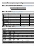
Page 15: ...dure 1 Turn the igni on ON 2 Press and release the valet bu on three 3 mes 3 The system will beep 1 one me indica ng you have accessed Bank 1 4 Each cycle of the Igni on OFF ON will advance to the nex...

Page 16: ...21 Factory Arm Output After Start GWR Igni on Accessory Start 22 Pulse A er Shutdown After Shutdown GWR Igni on Accessory Start 23 Addi onal Unlock Pulse NA Features Feature Bank 3 Op ons Quick Refere...

Page 17: ...lease the valet push bu on switch The parking lights will turn on for two 2 seconds and one 1 long chip will indicate that the learned tach signal is stored and the unit has exited tach learn mode Pro...

Page 18: ...be selectable on the fly without entering the programming feature banks 1 Turn the igni on ON OFF ON OFF 2 Press and hold valet bu on for ve 5 seconds The system will respond with one 1 flash for ON...

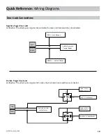
Page 19: ...are ac vated Negative Trigger Door Locks Verification The vehicle wires register Ground when the Lock and Unlock switches are ac vated Lock Unlock Vehicle Door Lock Control Relays RED Lock Output GREE...

Page 20: ...sitive Multiplex Door Locks Relays required Verification The vehicle wire registers variable 12V values when the Lock and Unlock switches are ac vated Please consult the vehicle speci c wire and loca...

Page 21: ...d Aftermarket Actuators Relays and door lock actuators required Lock Unlock 87 87a 86 85 30 87 87a 86 85 30 Fused 12 Volt Battery Souce Fused 12 Volt Battery Souce RED Lock Output Green Unlock Output...

Page 22: ...d Parking Light 87 Input 3 Yellow Black Igni on Output For Alarm 4 Black Ground Input 4 Pin Light P Replacement Part 4120463 Replacement Part 4120467 1 3 5 2 4 6 1 3 2 4 Replacement Part 4120465 Repla...

Reviews: