82
Prestigio Cavaliere 141
Technical Service Manual
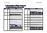
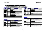
5. Pin Descriptions of Major Components
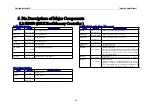
Ster eo Glasses Inter face
Nam e Pin
Attr
Sign al
Descr iption
CSYNC
O
3.3V - M
Stereo Clock
RSYNC
O
3.3V - M
Stereo Right
LSYNC
O
3.3V - M
Stereo Left
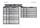
SiS MuTIOL Inter face
Name
Pin Attr
Signal Description
PIPE#
I
1.5V/3.3V - M
AGP Pipeline Request
SBA[7:0]
I/O
1.5V/3.3V - M
Side Band Address
RBF#
I
1.5V/3.3V - M
Read Buffer Full
WBF#
I
1.5V/3.3V - M
Write Buffer Full
AD_STB[1:
0]
I/O
1.5V/3.3V - M
AD Bus Strobe
AD_STB[1:
0]#
I/O
1.5V/3.3V - M
AD Bus Strobe Compliment
SB_STB
I
1.5V/3.3V - M
Side Band Strobe
SB_STB#
I
1.5V/3.3V - M
Side Band Strobe Compliment
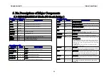
Test Mode/Har dwar e Tr ap/Power Management
Nam e Pin
Attr
Sign al
Descr iption
DLLEN#
I/O
3.3V/5V - M
Hardware T rap pin (refer to section 5)
DRAM_SEL
I
3.3V/5V - AUX
Hardware T rap pin (refer to section 5)
T RAP[1:0]
I
3.3V/5V - M
Hardware T rap pins (refer to section 5)
ENT EST
I
3.3V/5V - M
T est Mode enable pin
T EST MOD
E[2:0]
I
3.3V/5V - M
T est Mode select pin
Nand T ree T est: 100
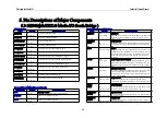
AUXOK
I
3.3V - AUXI
Auxiliary Power OK :
T his signal is supplied from the power source of resume well. It
is also used to reset the logic in resume power well. If there is
no auxiliary power source on the system, this pin should be tied
together with PWROK.
PCIRST #
I
3.3V - AUXI
PCI Bus Reset :
PCIRST # is supplied from SiS MuT IOL Media IO SiS961.
PWROK
I
3.3V - AUXI
Main Power OK :
A high-level input to this signal indicates the power being
supplied to the system is in stable operating state. During the
period of PWROK being low, CPURST and PCIRST # will all
be asserted until after PWROK goes high for 24 ms.
5.2 SiS650 (IGUI Host Memory Controller )

