88
Prestigio Cavaliere 141
Technical Service Manual
5. Pin Descriptions of Major Components
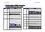
Keyboar d Contr ol Inter face
Name
Pin Attr
Signal Descr iption
KBDAT /
GPIO15
I/OD
O/OD
3.3V/5V -AUX
Keyboar d Dada:
When the internal keyboard controller is enabled, this pin is
used as the keyboard data signal.
KBCLK /
GPIO16
I/OD
O/OD
3.3V/5V -AUX
Keyboar d Clock:
When the internal keyboard controller is enabled, this pin is
used as the keyboard clock signal.
PMDAT /
GPIO17
I/OD
O/OD
3.3V/5V -AUX
PS2 Mouse Data:
When the internal keyboard and PS2 mouse controllers are
enabled, this pin is used as PS2 mouse data signal.
PMCLK /
GPIO18
I/OD
O/OD
3.3V/5V -AUX
PS2 Mouse Clock:
When the internal keyboard and PS2 mouse controllers are
enabled, this pin is used as the PS2 mouse clock signal.
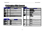
MAC Inter face
Name
Pin Attr
Signal Descr iption
RXER
I
3.3V/5V -AUX
RX Packet Er ror
This event is signaled after the last received descriptor in a
failed packet reception that has been updated with valid status.
MIICLK25M
I
3.3V/5V -AUX
PHY 25MHz Clock Input:
This pin provides the 25MHz clock signal input to the built-in
oscillator.
MDC O
3.3V -AUX
Management Data Clock:
Clock signal with a maximum rate of 2.5MHz used to transfer
management data for the external physical unit on the
MIIMDIO pin.
TXD[0:3]
I
3.3V/5V -AUX
Receive Data:
This is a group of 4 data signals aligned on nibble boundaries
which are driven synchronous to the RXCLK by the external
physical unit.
TXEN
O
3.3V -AUX
Tr ansmit Data:
This is a group of 4 data signals which are driven synchronous
to the TXCLK for transmission to the external physical unit.
RXD[0:3]
I
3.3V/5V -AUX
Receive Data:
This is a group of 4 data signals aligned on nibble boundaries
which are driven synchronous to the RXCLK by the external
physical unit.
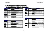
MAC Inter face Continue
Name
Pin Attr
Signal Description
TXEN
O
3.3V -AUX
Tr ansmit Enable:
When set to a 1, and the transmit state machine is idle, then the
transmit state machine becomes active. This bit will read back
as a 1 whenever the transmit state machine is active. After initial
power-up, software must insure that the transmitter has
completely reset before setting this bit
MDIO
I/O
3.3V/5V -AUX
Management Data I/O:
Bi-direction signal used to transfer management information for
the external physical unit. Requires external pull-up resistor.
RXDV
I
3.3V/5V -AUX
Receive Data Valid.
This indicates that the external physical unit is presenting
recovered and decoded nibbles on the RXD[3:0] and that
RXCLK is synchronous to the recovered data. This signal will
encompass the frame, starting with the Start-Of-Frame delimiter
and excluding the End-Of-Frame delimiter.
COL
I
3.3V/5V -AUX
Collision Detect:
This signal is asserted high asynchronous by the external
physical unit upon detection of a collision on the medium. It’ll
remain asserted as long as the collision condition persists.
CRS
I
3.3V/5V -AUX
Car r ier Sense:
This signal is asserted high asynchronously by the physical unit
upon detection of a non-idle medium.
RXCLK
I
3.3V/5V -AUX
Receive Clock
A continuous clock that is recovered from the incoming data.
During 100Mb/s operation RXCLK is 25MHz and during
10Mb/s this is 2.5MHz.
TXCLK
I
3.3V/5V -AUX
Tr ansmit Clock
A continuous clock that is sourced by the physical unit. During
100Mb/s operation RXCLK is 25MHz and during 10Mb/s this
is 2.5MHz.
5.3 SiS961(MuTIOL® Media I/O South Bridge )


