background image

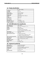
A.2  Display Specification 

14.1

 TFT LCD (AU) 

LCD Model 

AU 14.1  

LCD Type 

14.1

  TFT 

Display Pixels 

H1024 x V768 pixels 

Pixel Arrangement 

RGB vertical stripe 

Display colors 

262K Colors 

Module Size 

298.5(W) x 227.5(H) x 5.8(D) [mm] 

Weight 

Approx. 500g 

Contrast Ratio 

200:1 (typ.) 

Power Supply  

3.3V 

Response Time 

30ms (max) 

Operating Temperature 

0 to 50 degrees Celsius 

Storage Temperature 

-20 to 60 degrees Celsius 

A.5  DVD/ RW Combo Drive Specification 

Drive Manufacturer 

KME UJDA745 

Physical Dimension 

128.0 x 12.7 x 129 [mm] ( W * H * D ) 

Weight 

250g +/- 10g 

Loading 

Manual tray loading 

Ejection 

Manual eject using the eject button 
Auto eject using the eject command on software 

Host Interface 

Enhanced IDE (ATAPI) 

Average Access Time 

150ms Typ. 

Data Transfer Rate (burst) 

16.7 MByte/s (PIO Mode 4) 
16.7 MByte/s (Multi word DMA transfer mode-2) 
33.3 MByte/s (Ultra DMA transfer mode-2) 

Data Transfer Rate (sustained) 

Max. 2,100Kbyte/s (CD-RW) ; Max.3,600Kbyte/s(CD) 

Data Write Rate 

Max. 1,200Kbyte/s (CD-R) ; Max.600Kbyte/s(CD-RW) 

Starting Time 

Max. 10 sec (from stand by to ready) 

Data Buffer Capacity 

2MB 

Supply Voltage 

+5VDC +/-  15% 

MTBF 

50,000POH or more  

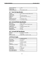
A.6  Keyboard Specification 

Keyboard Type 

ALLTOP PAN-international  

Type of key switch 

Membrane (PE) Switch  

Number of keys 

87 keys with embedded numeric keypad 

Compatibility 

Enhanced 101/102 emulation 

Travel 

3.0 mm 

±

 0.3 mm 

Keyboard Height 

6.5 

±

 0.3 mm  

7.0 

±

 0.3 mm (SPACE Key) 

TECHNICAL SERVICE MANUAL

Prestigio Cavaliere 142

100

Summary of Contents for CAVALIERE 142

Page 1: ...PRESTIGIO CAVALIERE 142 TECHNICAL SERVICE MANUAL...

Page 2: ...Bus port IEEE 1394 port advanced power management and more new multimedia features 1 2 Feature Highlights The Cavaliere 142 includes a variety of innovative features Category Specification Stepping CP...

Page 3: ...outh Bridge Intel ICH4 M Real Time Clock with 256 byte extended CMOS IBM AT Clock Calendar Alarm 14 Bytes K B Controller Mitsubishi M38859 LPC KBC Internal K B Touch Pad External K B or M S Supported...

Page 4: ...on ports Integrated physical layer transceivers with optional over current detection status on USB inputs IDE Interface Intel ICH4 M Fast IDE 2 ports Integrated multithreaded I O link mastering with r...

Page 5: ...valiere 142 Key component list in detail Keyboard Internal Keyboard 6 5mm Height 3 0mm Stroke 19mm Pitch Vendor ALLTOP PAN international Refer to the Cavaliere 142 Key component list in detail Speaker...

Page 6: ...D 2 54 KG OR 4 5 LBS WITH 14 1 LCD SYSTEM WITH HDD FDD CD ROM AND ONE LI ION BATTERY PACK Battery Handling Category Specification Remark Power On Li ion 3 5 h Battery Charging Max Change Current 1 7A...

Page 7: ...1 3 System Configuration Figure 1 1 System Configuration Diagram TECHNICALSERVICEMANUAL PrestigioCavaliere142 6...

Page 8: ...The Inside side of the Notebook Color LCD Display Built in Stereo Speakers Easy Buttons Integrated Microphone Status LED Indicator Built in Stereo Speakers Power On Resume Button Keyboard Touchpad Poi...

Page 9: ...embedded numeric keypad 7 hot keys inverted T cursor arrow keys and separate page screen control keys Wide extra space below the keyboard panel for your wrist or palm to sit on comfortably during typi...

Page 10: ...by pressing this button You can simplify several procedures in entering into Outlook 98 2000 2002 environment Status LED Indicator Located just in front of the palmrest assembly you will find three L...

Page 11: ...green light indicates that the system is accessing or retrieving data by wireless device Caps Lock When LED in green light indicates that the Caps Lock key on the keyboard is activated When activated...

Page 12: ...r only using the display hot key USB Port The Universal Serial Bus USB port allows you to connect up to 127 USB equipped peripheral devices for example printers scanners and so on to your notebook com...

Page 13: ...you connect various PC cards such as memory card Supports both 3V 5V 32 bit CardBus and 16 bit PC cards 1 4 5 The Right Side of the Notebook CD ROM DVD ROM CD RW module Locking Device Keyhole Figure...

Page 14: ...s When you connect the AC adapter it charges the battery whether or not the notebook computer is powered on There is an LED on the AC adapter to indicate if DC power is already available 1 5 2 Battery...

Page 15: ...est POST If an error occurs an error message will be displayed on the screen and you will then be prompted to run the Setup Program As the POST Power On Self Test executes during the boot up process t...

Page 16: ...ime Allows you to change the system time using the hour minute second format of the computer Enter the current time for reach field and use the Tab Shift Tab or Enter key to move from one field or bac...

Page 17: ...ield reports the amount of base or conventional memory found by the BIOS during Power On Self Test POST Extended Memory This field reports the amount of extended memory found by the BIOS during Power...

Page 18: ...can select different drive types as CD ROM User Auto or None by pressing Space bar Set this option to Auto so your computer will automatically detect the drive type during power on Set this option to...

Page 19: ...will be reduced I O Device Configuration Lets you configure input output device such as Serial Port Parallel Port and Floppy disk controller I ODeviceConfigurationSub Menu PhoenixBIOS Setup Utility M...

Page 20: ...is notebook Parallel port Allows you to select the Enabled Disabled or Auto option for enabled or disabled this port or automatically sensed by BIOS or OS If you select Enable you also need to set the...

Page 21: ...n re enter it for confirmation Set User Password This field is only available when Supervisor Password has set Enter the user password when boot the system or resume from suspend mode But if the Write...

Page 22: ...ress to move up the device in the list or press to move down the device in the list To exit from this menu press Esc 1 6 6 How to ExittheSetupProgram There are two choices to escape from the Setup pro...

Page 23: ...BIOS any customized settings you made are lost To upgrade the BIOS 1 Insert the BIOS Update diskette into the diskette drive 2 Power on the system with the diskette in the diskette drive 3 On the DOS...

Page 24: ...ess LAN utility i Visit Prestigio website http www prestigio com for the latest driver updates 2 2 1 Installing Windows XP from CD DVD ROM This section provides Windows XP installation guide from the...

Page 25: ...the New Hardware Found Message Box 4 In the Found New Hardware Wizard message box which shows searching Multimedia Audio Controller driver Click Next to proceed to the next step 5 Select Search for a...

Page 26: ...oller click Uninstall OK then Scan for hardware changes buttons to appear the New Hardware Found Message Box 4 In the Found New Hardware Wizard message box which shows searching Ethernet Controller dr...

Page 27: ...SW1 Keyboard Type Select K B Type Pos 1 POS 2 US KEYBOARD OFF OFF JP KEYBOARD ON OFF UK KEYBOARD ON ON DVDSEL ODD select Pos 5 KME UJDA745 DVD CD RW Combo ON BIOS Crisis BIOS Crisis Pos 4 Default OFF...

Page 28: ...h AC adapter and the battery pack from the notebook unit 2 There are four screws on the bottom case and that should be removing as the picture indicated Figure 2 2 Location of screws 3 Remove keyboard...

Page 29: ...s as shown in the picture below and then remove Middle plate Figure 2 5 Remove Middle plate 7 Release four screws and one cable as shown in the picture below and then remove heat sink plate and Fan TE...

Page 30: ...l automatically detect the type of the CPU which just be installed 2 3 3 Memory Upgrade Procedure The notebook computer offers two memory slot using DDR DIMM at 128MB 256MB 512MB and 1024MB DDR RAM Tw...

Page 31: ...the socket Press down on the edge of the DIMM until the locking tabs on the sides snap into place securing the module 5 To remove a DIMM press the locking tabs away from the sides of the module until...

Page 32: ...ATFORM BIN into the diskette along with the BIOS ROM file 2 Restart the computer and boot from the diskette At the DOS prompt type the command PHLASH BIOSfile ROM to activate Flash BIOS programming ut...

Page 33: ...System auto detects LCD or CRT presence on boot and lid closed Support Panning while LCD in a display resolution greater than supported Support Microsoft Direct 3D Support AGP 4x BUS Hard Disk Enhance...

Page 34: ...IA Controller RICOH R5C551 Audio Chip Intel South Bridge Integrated Audio Codec Intel ICH4 Keyboard Controller Misubishi M3885x PMU Controller NEC PMU08 ROM BIOS SST 49LF004A Clock Generator IMI CY283...

Page 35: ...ntrol in LCD only CRT only and simultaneous mode The VGA BIOS will allow mode sets of resolutions greater than the panel size but only show as much mode display as will fit on the panel Supported stan...

Page 36: ...cked 60 72 75 85 100 2MB 115h 800 x 600 32 bit Unpacked 60 72 75 85 100 2MB 117h 1024 x 768 16 bit Packed 43 I 60 70 75 85 100 2MB 118h 1028 x 768 32 bit Unpacked 43 I 60 70 75 85 100 4MB 11Ah 1280 x...

Page 37: ...packed 75 2MB Note The modes may not be available Their availability should be determined by VESA function calls PanelTypeInitialization The VGA BIOS will issue INT 15h function call during POST This...

Page 38: ...t off the volume using both software and hardware 3 3 7 PCMCIA The PCMCIA controller chip of the notebook provides the following features Individually accessed dual buffer implementation Support for 2...

Page 39: ...s resources are as follows Device Connect Type Resources I O IRQ DMA Memory DMA Controller Static 00 0F 81 8F DMA5 Interrupt Controller Static 20 21 A0 A1 IRQ2 System Timer Static 40 43 IRQ0 RTC Stati...

Page 40: ...s master Allocation Arbiter Signal Agents Master Function Use REQ00 GNT00 REQ10 GNT10 RICOH Card Bus Controller REQ20 GNT20 REQ30 GNT30 3 3 12 SMBus Devices The SMBus is a two wire interface through w...

Page 41: ...trol Port 0A0 0A1 8259 2 0B2 Advanced Power Management Control Port 0B3 Advanced Power Management Status Port 0C0 0DF 8237 2 0F0 0FF Math Coprocessor 170 177 IDE Secondary Command Block 1F0 1F7 IDE Pr...

Page 42: ...sk Drive IRQ 7 IRQ 8 RTC Alarm IRQ 9 ACPI IRQ10 LAN Modem or Combo Card Bus IEEE 1394 IRQ11 Reserved for PCMCIA card IRQ12 Glide Pad IRQ13 FPU FERR IRQ14 Hard Disk Drive IRQ15 CD ROM or DVD ROM 3 3 13...

Page 43: ...emar k GPIO B6 PM_SLP_S 10 1 I Suspend Plane A control for ICH4 0 POS STR and STD suspend state 1 not suspend state GPIO B5 N C No used GPIO B4 N C No used GPIO B1 N C 1 O No used GPIO B0 N C No use G...

Page 44: ...disassemble the machine in this state G1 Sleeping A computer state where the computer consumes a small amount of power user mode threads are not being executed and the system appears to be off from a...

Page 45: ...pt system memory CPU cache and chip set context are lost in this state Hardware maintains memory context and restores some CPU and L2 configuration context Control starts from the processor s reset ve...

Page 46: ...FLASH ROM HDD CD ROM USB Internal K B Glide Pad Audio AMP Fan 3VS SUSB ISA I F Power Clock Generator Buffer W137 RTCVCCS Nil RTC 3 4 2 Power Management Mode Transition Flow Chart From a user visible...

Page 47: ...ce component of the system under each power management mode PowerState Component Doze Stand By STR STD SOff CPU Stop Grant Stop Clock Power Off Power Off L2 CACHE ON Power Down Power Off Power Off Mon...

Page 48: ...ardware Power off HDD Hardware Power off FDD Hardware Power off KBC Software Controlled by M3885xM8 power down command PMU08 Sofeware Controlled by PMU08 power down command VGA VRAM Software Controlle...

Page 49: ...GPE Event from PMU08 The system will issue a beep to inform user while the following SCI alerted PMU08 Input Event GPE Event Handler ADPIN AC Plug In Out GPI12 AML Handler BAT0 Battery Plug In Out GP...

Page 50: ...ff Below 65oC Passive cooling Throttling CPU On Over 90 oC Throttling CPU Off Below 85oC Critical trip point System Shutdown Over 110 oC 3 5 Battery Management 3 5 1 BatterySub system The charger will...

Page 51: ...er management is disabled The function of power on or Resume will be inhibited until the battery Low Low condition is removed 3 5 4 ACAdapter When plug in the AC adapter the system will do the followi...

Page 52: ...o host Interrupt on OBF 1 1 EC_SC W Command byte Header Interrupt on IBF 0 2 EC_DATA W Address byte to write Interrupt on IBF 0 Write Embedded Controller WR_EC 0x81 3 EC_DATA W Data to write Interrupt...

Page 53: ...W DATA 15 0 1 0xffff 0x0000 0xfffe mV 0xffff Unknown 0Ah 3 Design capacity of Warning R W DATA 15 0 1 0xffff 0x0000 0xfffe mWh 0xffff Unknown 0Ch 3 Design capacity of Low R W DATA 15 0 1 0xffff 0x0000...

Page 54: ...battery is critical Empty 1Ch 3 Battery Present rate R W DATA 15 0 1 0xffff 0x0000 0xfffe mW 0xffff Unknown 1Eh 3 Battery Remainin g Capacity R W DATA 15 0 1 0xffff 0x0000 0xfffe mWh 0xffff Unknown 1...

Page 55: ...1 0 Logic Default Description 6Ch PMU_LO W_ ADR R W DATA 7 0 6Dh PMU_HI G_ ADR R W DATA 15 8 6Eh CHECK_ SUM R W DATA 7 0 PMU Access 6Fh PMU_DA TA R W DATA 7 0 These registers are available when PMU s...

Page 56: ...7 SMB_PT CL R W PROTOCOL 7 0 71h 7 SMB_ST S R W D O N E A L R M R E S STATUS 4 0 72h SMB_AD DR R W ADDRESS 6 0 R E S 73h SMB_CM D R W COMMAND 74h to 93h SMB_DA TA 0 31 R W DATA 94h SMB_BC NT R W RES 7...

Page 57: ...Reserved R W Don t care A7h SMB_Alert_ ADDR R W ADDRESS 6 0 R E S 0x00 SMBAlert output device address The alert response function is available when this register is cleared 0x00 only When the several...

Page 58: ...without unexpected event loss clear the corresponding bit flag only For this operation this register has special writing manner as follows STS_X STS_X AND Written data B0h EC_RUN_ ENB R W 0 Disable 1...

Page 59: ...Enable 0x00 BCh GPIO B_ EVT_POL R W 0 POL_B 6 0 0 Falling edge 1 Rising edge 0x00 BDh GPIO B_ WAKE_EN B R W 0 WAKE_ENB_B 6 0 0 Disable 1 Enable 0x00 BEh GPIO C_ DATA R W RES 7 4 4 DATA_C 3 0 BFh GPIO...

Page 60: ...ext SCI is not output until SCI_EVT is cleared 1 SCI is output when the command set is not executed and OBF 0 SCI_EVT shows the output SCI is for event notification 0 Runtime event ststus is reflected...

Page 61: ...arge ready CHGn 1 The nth battery is charged D1h BAT_DCH_ PRI R W RES 7 3 PAT 2 0 0x00 Battery discharge priority 0 2 1 1 1 2 2 2 1 3 2 1 4 1 2 5 1 2 6 Same as 0 7 Simultaneously discharge Read only T...

Page 62: ...lesser than this setting value the BTP2 is detected if event is enabled DDh To DFh Reserved R W Don t care E0h PMU_CONT R W RES 7 3 E C _ R E G B A Y _ L E D P O W _ L E D 0x00 EC_REG 1 BAY_LED 1 POW_...

Page 63: ...gister addressed A8h AFh Set the 00h to this register PMU control F1h To FFh Reserved R W Don t care 3 6 3 Security The user may enter up to eight standard text characters for a password The password...

Page 64: ...SIMMs two at a time With DIMMs you can install one DIMM at a time SODIMM is Small Outline Dual In line Memory Module used in notebook computers DMI Desktop Management Interface an API to enable softw...

Page 65: ...ion and Intel that supports burst mode data transfer rates of 33 3 MBps USB A new external bus standard that supports data transfer rates of 12 MBps A single USB port can be used to connect up to 127...

Page 66: ...Intel ICH4 M South PCI I F LPC I F ATA100 IDE I F Hub Link I F AC97 V2 2 I F RTC 2 0 1 1USB I F 10 100M LAN I F GPIO ACPI APIC Memory Support Memory DDR266 200 SDRAM 128 256 512MB 1G SO DIMM Memory S...

Page 67: ...MA 33 66 100 PIO mode 0 1 2 3 4 Internal HDD 2 5 9 5 mmH Pack Internal Optical Drive DVD Combo 8x DVD 8x CDR CDRW write 20x CD ROM 9 5mm type KME UJDA745 Toshiba SD R9022 Communication Internal Modem...

Page 68: ...On Off Fn F8 Brightness Up 8 level Fn F9 Brightness Down 8 level Fn F12 Scroll Lock Fn ArrowR Sound up Fn ArrowL Sound down Point Device SYNAPTICS TM41PDG351 1 Glide Pad AC Adapter LITEON PA 1600 05...

Page 69: ...Lock Yes Scr Lock Yes Num Lock Yes Mail arrival No RF Access Yes Security Kensington Lock Hole x1 PMU PMU08 Compliance PC2001 compliant ACPI compliant Plug and Play Support Auto Configuration 16bit I...

Page 70: ...4 2 System Hardware Block Diagram Figure 1 1 Cavaliere 142 Block Diagram TECHNICALSERVICEMANUAL PrestigioCavaliere142 69...

Page 71: ...chitectural enhancements over existing Intel mobile processors The following list provides some of the key features on this processor Supports Intel Architecture with Dynamic Execution High performanc...

Page 72: ...idth of up to 3 2 Gbytes second The processor system bus uses Advanced Gunning Transceiver Logic AGTL signal technology a variant of GTL signalling technology with low power enhancements The processor...

Page 73: ...pts signaled as upstream Memory Writes from PCI and Hub Interface MSI sent to the CPU through the System Bus From IOxAPIC in ICH4 M Provides redirection for upstream interrupts to the System Bus Hub I...

Page 74: ...e I O functions integrated into the ICH4 and the PCI peripherals obtain the bandwidth necessary for peak performance PCI Interface The ICH4 PCI interface provides a 33 MHz Rev 2 2 compliant implementa...

Page 75: ...channels Channels 5 7 are 16 bit channels Channel 4 is reserved as a generic bus master request The timer counter block contains three counters that are equivalent in function to those found in one 82...

Page 76: ...trol specification Half duplex performance is enhanced by a proprietary collision reduction mechanism See Section 5 2 LAN Controller B1 D8 F0 on page 5 78 for details RTC The ICH4 contains a Motorola...

Page 77: ...dard 144 pin SODIMM modules at 128MB 256MB 512MB and 1GMB sizes Memory modules are DDR 200 266 SDRAM type 4 8 2 Video Memory The video memory of the notebook is using share system memory with 8 32MB U...

Page 78: ...p to 1920x1440 at 60 Hz Dual independent pipe support Concurrent Different images and native display timings on each display device Simultaneous Same images and native display timings on each display...

Page 79: ...elization rules Anti Aliased Lines support Sprite Points support Provides the highest sustained fill rate performance in 32 bit color and 24 bit W mode High quality performance Texture Engine 266 Mega...

Page 80: ...st controller is compliant with the 2000 PC Card Standard This standard incorporates the new 32 bit CardBus while retaining the 16 bit PC Card specification as defined by PCMCIA release 2 1 CardBus is...

Page 81: ...ibility for PC Cards that interface with advanced notebook designs R5C551 FEATURES Slot Solution Supports only one PCMCIA 2 1 and JEIDA 4 2 R2 cards or 2 CardBus cards ACPI PCI Bus Power Management In...

Page 82: ...ne line inputs and headphone outputs 4 13 Keyboard and Pointing Device The Keyboard Subsystem of the notebook is implemented on the Motherboard and Keyboard Assembly using the Mitsubishi M38859 keyboa...

Page 83: ...continues to coast in the indicated direction when the finger is held against the edge 4 14 Disk Drives Subsystem The disk drives subsystem implemented on the Motherboard and on the associated interna...

Page 84: ...s with the PMU08 via the SMBus interface The SMBus host should be first initialized before starting the transaction The following is the procedure for system communication with PMU08 1 Enable SMBus in...

Page 85: ...C Universal Synchronous Asynchronous Receiver Transmitter USART SCI Brown out detection circuitry for Brown out Reset BOR 2K bytes program memory 128 bytes data memory 22 I O pin 8 interrupt sources T...

Page 86: ...mmercially available computer cleaning kit i Never use alcohol petroleum based solvents or harsh detergents to clean the notebook Also do not spray any liquids directly on the computer case keyboard o...

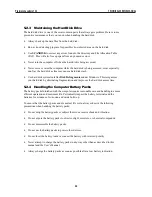
Page 87: ...ves the hard disk access time 5 2 4 Handling the Computer Battery Packs The battery packs furnished with the computer require reasonable care and handling to ensure efficient operation and maximum lif...

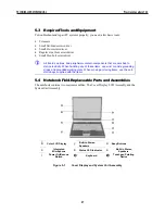
Page 88: ...t or ankle grounding straps and grounded working mats When moving or storing items use the anti static bags supplied with the items 5 4 Notebook Field Replaceable Parts and Assemblies The notebook con...

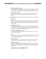
Page 89: ...LCD FPC Cable The LCD FPC cable is used to convert output signals from the motherboard in driving the LCD display screen The cable is connected to the back of the LCD Panel 5 4 2 System Unit Assembly...

Page 90: ...it located just below the keyboard The HDD is secured by only one screw The HDD module is a 2 5 inch hard disk drive with a maximum height of 9 5mm The hard drive module assembly is attached to the mo...

Page 91: ...ng the Battery Pack The procedure for removing and replacing the battery pack is as follows To remove the battery pack slide the latch to right side and hold it then take out the battery pack with you...

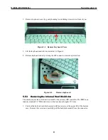
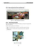
Page 92: ...igure 5 5 Remove keyboard 5 5 3 Removing the Internal Hard Disk Drive The notebook provides a built in hard disk for the primary IDE controller The HDD is an industry standard 2 5 IDE disk drive with...

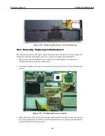
Page 93: ...bracket plate Figure 5 7 Screws Locations of the frame HDD bracket plate 5 5 4 Removing the LCD Panel The procedure for removing the LCD Panel is as follows 1 There are three screws as the picture in...

Page 94: ...wo hex bolds of rear side for the system unit Figure 5 9 Two Screws and two hex bolds 3 Removing the two screws of LCD connector and one LCD cable Figure 5 10 Two Screws and one LCD cable 2 Slowly pul...

Page 95: ...ures Intel Pentium M uFC PGA Processors It is located on the upper left side of the system motherboard To install or replace the CPU follow the steps below 1 Before removing the CPU module you need fi...

Page 96: ...shown 1 To remove the top cover you also need to remove the three screws and four cables one is called MDC cable the other one is Microphone cable and another one is MDC FPC and also G P FPC from the...

Page 97: ...board you need first to disassemble the all basis unit modules mentioned in the previous sections 2 On the motherboard there are two screws and one hex bolt Remove these hex bolts and screws Figure 5...

Page 98: ...ntroller Integrated DMA Controller 1 1 2 0 Universal Serial Bus Host Controller Integrated 10 100M Fast Ethernet MAC Controller Integrated Audio Controller with AC97 V2 2 Interface Advanced Power Mana...

Page 99: ...ate firmware version 2 14 PMU New PMU08 Mitsubishi M38859FFHP Embedded Controller VGA Controller Embedded in Intel Montara GM High Performance and high quality 3D accelerator Integrated dual DVO bridg...

Page 100: ...th optional over current detection status on USB inputs IDE Interface Intel ICH4 M Fast IDE 2 ports Integrated multithreaded I O link mastering with read pipelined streaming Dual independent IDE chann...

Page 101: ...eject using the eject command on software Host Interface Enhanced IDE ATAPI Average Access Time 150ms Typ Data Transfer Rate burst 16 7 MByte s PIO Mode 4 16 7 MByte s Multi word DMA transfer mode 2...

Page 102: ...ction Mode V 90 Kbps Speakerphone Full duplex speakerphone FDSP Fax Transmission Way Half Duplex Modem Speed 56 Kbps Modulation Format V 90 PCM A 9 On board LAN Specification LAN Type Intel ICH4 M Int...

Page 103: ...cy 30 70KHz Efficiency 75 min Brightness Control Voltage 0 94 1 86V A 12 DC DC Specification Controller PMU 08 Input Voltage 8 20V Output Current 4A 5V 4A 3 3V 100mA 12V Frequency 200KHz Support Mode...

Page 104: ...without condensation 5 to 90 RH without condensation Shock Non operating Unpacked Acceleration 30G 50G Duration Time 11ms No of Times 3 Times Direction 6 face Drop Package Drop Height 91cm under 10Kg...

Page 105: ...Module HDD _30GB _FUJ 1 x 25 03286 00 N A N A N A 11 HDD 30GB FUJ 1 x 23 20754 06 45 12Mth FIC 12 SCREW 1 x 24 10524 00 30 N A N A 13 FRAME HDD 1 x 24 51170 00 30 N A N A 14 FRAME HDD 1 x 24 52171 00...

Page 106: ...FOR 14 1 1 x 80 40759 00 30 N A N A 46 LCD COVER BACK FOR 14 1 1 x 80 50209 00 30 N A N A 47 LCD LATCH 24 81401 00 30 48 Module LCD TFT 14 1 HSD 1 x 56 10656 00 N A N A N A 49 LCD 14 1 HSD 1 x 71 1068...

Page 107: ...w w w p r e s t i g i o c o m...

Reviews: