3.4.1 System Power Plane
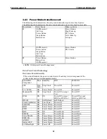
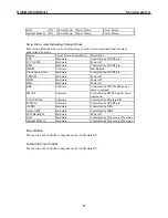
The system components are grouped as the following parties to let the system to control the
On/Off of power under different power management modes.
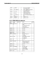
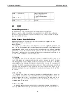
The power plane is divided as following:
Power Group Power
Control Pin
Controlled Devices
+B
Nil
IMM, (9V~20V)
+3VA
Nil
RTC I/F, PMU08
+12V
PWRON PCMCIA Card, AC97 Codec
+5V
PWRON PCMCIA Slot 5V
+3V
PWRON VGA, PCMCIA, PCMCIA Slot 3V, DRAM, Twister(DRAM
I/F), M3885x, MAX3243
+5VS
SUSB#
FLASH ROM, HDD, CD-ROM, USB, Internal K/B, Glide Pad,
Audio AMP, Fan
+3VS
SUSB#
ISA I/F Power, Clock Generator & Buffer (W137)
+RTCVCCS Nil
RTC
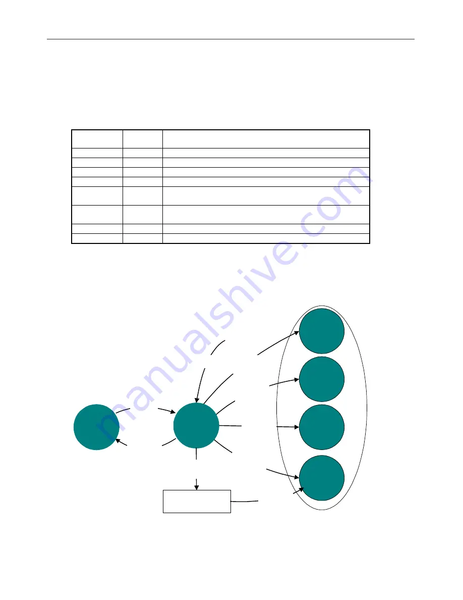
3.4.2 Power Management Mode Transition Flow Chart
From a user-visible level, the system can be thought of as being one of the states in the
following diagram:
SLP_TYPx=S1
and
SLP_EN
S1
Sleeping
S2
Sleeping
S3
Sleeping
SLP_TYPx=S5
and
SLP_EN
or
PWRBTN_OR
Wake
Event
S4
Sleeping
ACPI
Boot
(SCI_EN=1)
G2 (S5) -
Soft Off
SLP_TYPx=S2
and
SLP_EN
SLP_TYPx=S3
and
SLP_EN
SLP_TYPx=S4
and
SLP_EN
G0 (S0) -
Working
G1
S4BIOS_REQ
to
SMI_CMD
OEM S4 BIOS
Handler
SLP_TYPx=S4
and
SLP_EN
TECHNICAL SERVICE MANUAL
Prestigio Cavaliere 142
45

