background image

2.Disassembly

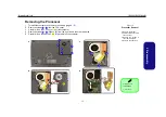
Removing the Keyboard

1. Turn 

off

 the computer, and remove the battery (

page 2 - 5

).

2. Press the 

three

 keyboard latches at the top of the keyboard to elevate the keyboard from its normal position


(you 

may need to use a small screwdriver to do this).

3. Carefully lift the keyboard 

 up, being careful not to bend the keyboard ribbon cable 

 (

Figure 10

c

).

4. Disconnect the keyboard ribbon cable 

 from the locking collar socket 

.

4

5

5

6

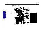
Figure 10

Keyboard Removal

a. Press the three latches

to release the keyboard.

b. Lift the keyboard up.
c. Disconnect the cable

from the locking collar.

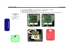
Re-Inserting the Key-

board

When re-inserting the
keyboard firstly align
the 

five

 keyboard tabs

(

Figure 10b

) at the

bottom of the keyboard
with the slots in the
case.

a.

c.

b.

1

2

3

5

6

4

4

Keyboard Tabs

d.

4

4. Keyboard

TECHNICAL SERVICE MANUAL

Prestigio Nobile 158W

15

Summary of Contents for Nobile 158W

Page 1: ...PRESTIGIO NOBILE 158W TECHNICAL SERVICE MANUAL ...

Page 2: ...ted transmitted or reduced to any machine readable form without prior consent from the vendor manufacturer or creators of this publica tion except for copies kept by the user for backup purposes Brand and product names mentioned in this publication may or may not be copyrights and or registered trademarks of their respective companies They are mentioned for identification purposes only and are not...

Page 3: ... or upgrading components of Prestigio Nobile 158W notebook PC The following information is included Chapter 1 Introduction provides general information about the location of system elements and their specifications Chapter 2 Disassembly provides step by step instructions for disassembling parts and subsystems and how to upgrade elements of the system Appendix A Part Lists Appendix B Schematic Diag...

Page 4: ...remote risk of elec trical shock from lightning 3 Do not use the telephone to report a gas leak in the vicinity of the leak 4 Use only the power cord and batteries indicated in this manual Do not dispose of batteries in a fire They may explode Check with local codes for possible special disposal instructions 5 This product is intended to be supplied by a Listed Power Unit DC Output 20V 3 5A CAUTIO...

Page 5: ...t to save your work Remember to periodically save your data as data may be lost if the battery is depleted Do not expose the computer to any shock or vibration Do not place it on an unstable surface Do not place anything heavy on the computer Do not expose it to excessive heat or direct sunlight Do not leave it in a place where foreign matter or mois ture may affect the system Don t use or store t...

Page 6: ...e access to a compatible outlet have a qualified electrician install one When you want to unplug the power cord be sure to disconnect it by the plug head not by its wire Make sure the socket and any extension cord s you use can support the total current load of all the connected devices Before cleaning the computer make sure it is disconnected from any external power supplies Use only approved bra...

Page 7: ... of batteries carefully Batteries may explode or leak if exposed to fire or improperly handled or discarded Keep the battery away from metal appliances Affix tape to the battery contacts before disposing of the battery Do not touch the battery contacts with your hands or metal objects Battery Disposal The product that you have purchased contains a rechargeable battery The battery is recyclable At ...

Page 8: ...ation User s Manual on CD This describes the notebook PC s features and the procedures for operating the computer and its ROM based setup pro gram It also describes the installation and operation of the utility programs provided with the notebook PC TECHNICAL SERVICE MANUAL Prestigio Nobile 158W 7 ...

Page 9: ...VD Device 2 12 Removing the Processor 2 13 Removing the Keyboard 2 15 Part Lists A 1 Part List Illustration Location A 2 Top Model A A 3 Bottom Model A A 4 LCD Model A A 5 CD ROM Drive SAMSUNG Model A A 6 Combo Drive SAMSUNG Model A A 7 DVD Dual Drive PIONEER Model A A 8 DVD ROM Drive TOSHIBA Model A A 9 DVD RW Drive TOSHIBA Model A A 10 Top Model B A 11 Bottom Model B A 12 LCD Model B A 13 CD ROM...

Page 10: ...F A B 26 M10 MEM I F B B 27 M10 VGA Connector B 28 Panel CON B 29 VGA DDR DRAM Termination B 30 Audio Out Off Board B 31 BTVCC 1 5V 1 8VS B 32 V_CORE B 33 VDD3 VDD5 12V 3V 5V B 34 2 5VS 1 25VS 5VS 3VS B 35 Charger B 36 SMSC LPC47N217 LPC I F B 37 Click Board B 38 Hot Key B 39 USB COM1 B 40 Multi Function Board LED B 41 TECHNICAL SERVICE MANUAL Prestigio Nobile 158W 9 ...

Page 11: ...x Windows NT 4 0 Windows 2000 Windows XP OS 2 Warp UNIX etc have their own manuals as do application software e g word processing and database programs If you have questions about those programs you should consult those manuals The Nobile 158W notebook is designed to be upgradeable See Disassembly on page 2 1 for a detailed description of the upgrade procedures for each specific component Please n...

Page 12: ...ity Radeon 9700 High Performance Chip Integrated 128 bit 2D 3D Graphics Accelerator Advanced HW Acceleration for DVD Playback Fully DirectX 9 Support 128MB DDR SGRAM External Video Memory Dual View Display Monitor External Display Supporting Resolution up to 1600 1200 UXGA Storage One Changeable 12 7mm h Optical Device CD ROM DVD ROM CD RW DVD RW Combo DVD Dual etc One Changeable Primary 2 5 9 5mm...

Page 13: ...PRO Wireless 2100 802 11b OR Intel PRO Wireless 2200BG 802 11b g Mini PCI WLAN Module Option USB Video Camera Module Factory Option Bluetooth 1 1 MDC Module Factory Option Indicators LED Indicators System Activity Suspend Power On AC In Battery Charging Battery Full Num Lock Caps Lock Scroll Lock email WLAN Bluetooth HDD CD ROM Power Management Supports ACPI 2 0 Supports Hibernate Standby Modes Su...

Page 14: ...DVD Dual Drive Module Software DVD Player Intel PRO Wireless 2100 802 11b Mini PCI WLAN Module Option Intel PRO Wireless 2200BG 802 11b g Mini PCI WLAN Module Option Bluetooth 1 1 MDC Module Factory Option USB VIdeo Camera Module Factory Option Feature Specification TECHNICAL SERVICE MANUAL Prestigio Nobile 158W 4 ...

Page 15: ...Built In PC Camera 2 LCD 3 LED Power Communication Indicators 4 Speakers 5 Close Cover Switch 6 LED Status Indicators 7 Power Button 8 Keyboard 9 Built In Microphone 10 TouchPad and Buttons 11 Hot Key Buttons 2 6 3 4 1 7 10 4 8 5 11 4 4 7 6 9 TECHNICAL SERVICE MANUAL Prestigio Nobile 158W 5 ...

Page 16: ...5 Microphone In Jack 6 Headphone Out Jack 7 Hot Key Buttons 1 1 7 2 4 5 6 3 Figure 3 Left Side View 1 Vent Fan Intake 2 External Monitor VGA Port 3 S Video Out Port 4 RJ 11 Phone Jack 5 RJ 45 LAN Jack 6 2 USB 2 0 Ports 7 Infrared Transceiver 8 PC Card Slot 9 PC Card Slot Eject Button 3 4 1 5 2 6 7 8 9 TECHNICAL SERVICE MANUAL Prestigio Nobile 158W 6 ...

Page 17: ...al Locator Right Side Rear Views 4 1 2 3 Figure 4 Right Side View 1 USB 2 0 1 1 Port 2 Serial Port 3 Optical Device Bay 4 DC In Jack Figure 5 Rear View 1 Security Lock Slot 1 TECHNICAL SERVICE MANUAL Prestigio Nobile 158W 7 ...

Page 18: ...PU Bay Cover 4 RAM Module Cover 5 Hard Disk WLAN Bluetooth Module Cover 6 Optical Device Removal Cover Overheating To prevent your com puter from overheating make sure nothing blocks the vent fan in takes while the com puter is in use 1 2 4 6 3 1 1 5 TECHNICAL SERVICE MANUAL Prestigio Nobile 158W 8 ...

Page 19: ...view Top Key Parts Figure 7 Mainboard Top Key Parts 1 PC Card Assembly 2 Northbridge Intel 855PM 3 Southbridge 82801DBM 4 H8 5 LPC Super I O NS PC87383 6 Clock Generator 1 2 3 4 5 6 TECHNICAL SERVICE MANUAL Prestigio Nobile 158W 9 ...

Page 20: ...nboard Bottom Key Parts 1 CPU Socket no CPU installed 2 Memory Slots no memory installed 3 ATI Mobility Radeon 9700 4 Flash BIOS ROM 5 CardBus PCI1620 6 LAN Controller RTL8110S 32 7 ALC202 Audio Codec 1 2 3 4 5 6 7 TECHNICAL SERVICE MANUAL Prestigio Nobile 158W 10 ...

Page 21: ...an Cable Connector JFAN1 4 Keyboard Cable Connector JKB1 5 TouchPad Cable Connector JTP1 6 Microphone Cable Connector JMIC1 7 Power Cable Connector CN1 8 CCD Cable Connector JCCD1 9 Multi Function Board CN3 10 CMOS Battery Cable Connector JBAT1 11 Speaker Cable Connector JSPK2 7 8 4 6 1 2 3 9 11 10 5 TECHNICAL SERVICE MANUAL Prestigio Nobile 158W 11 ...

Page 22: ... CD ROM Connector J3 3 Fan Cable Connector JFAN2 4 Hard Disk Connector JHDD1 5 Mini PCI Wireless Lan Module Connector JMINIPCI1 6 Modem Module Connector J4 7 Hot Key Cable Connector CN6 8 Modem Cable Connector JMODEM1 9 LCD Panel Cable Connector JLCD1 1 2 3 4 5 6 8 7 9 TECHNICAL SERVICE MANUAL Prestigio Nobile 158W 12 ...

Page 23: ... box in the page margin Information contained under the figure will give a synopsis of the sequence of procedures involved in the disassembly procedure A box with a lists the relevant parts you will have after the disassembly process is complete Note The parts listed will be for the dis assembly procedure listed ONLY and not any previous disassembly step s required Refer to the part list for the p...

Page 24: ...nnector is oriented in the same way The pin1 side is usually not indicated Pressure sockets for multi wire connectors To release this connector type grasp it at its head and gently rock it from side to side as you pull it out Do not pull on the wires themselves When replacing the connection do not try to force it The socket only fits one way Pressure sockets for ribbon connectors To release these ...

Page 25: ...s Turn off and detach any peripherals 7 Beware of static discharge ICs such as the CPU and main support chips are vulnerable to static electricity Before handling any part in the computer discharge any static electricity inside the computer When handling a printed circuit board do not use gloves or other materials which allow static electricity buildup We suggest that you use an anti static wrist ...

Page 26: ... the HDD page 2 6 3 Remove the modem page 2 8 To remove the Wireless LAN 1 Remove the battery page 2 5 2 Remove the HDD page 2 6 3 Remove the wireless LAN page 2 9 To remove the System Memory 1 Remove the battery page 2 5 2 Remove the system memory page 2 10 To remove the Optical Device 1 Remove the battery page 2 5 2 Remove the Optical device page 2 12 To remove the Processor 1 Remove the battery...

Page 27: ...irection of the arrow towards the unlock symbol and hold it in place as shown in Figure 1b 4 Slide the Battery out of the computer s battery bay Figure 1c 3 Battery 1 2 3 1 a 3 b c 2 Figure 1 Battery Removal a Locate the battery re lease latch b Slide the latch to the left and hold c Slide the battery out TECHNICAL SERVICE MANUAL Prestigio Nobile 158W 5 ...

Page 28: ...rd disk and HDD bay cover 3 Remove screws and remove the HDD bay cover Figure 2 HDD Assembly Removal a Locate the HDD bay cov er b Remove the 7 screws c Remove the cover 1 2 8 1 1 HDD Bay Cover 7 Screws HDD System Warning New HDD s are blank Be fore you begin make sure You have backed up any data you want to keep from your old HDD You have all the CD ROMs and FDDs required to in stall your operati...

Page 29: ...isk Figure 3c 7 Reverse the process to install a new hard disk pay careful attention to the orientation of the disk under the cover 1 2 3 6 7 8 4 b a 8 3 1 2 6 5 c 7 Figure 3 HDD Assembly Removal Cont a Slide out the HDD as sembly b Lift the HDD assembly out of the bay c Remove the screws and separate the cover and HDD 7 HDD Cover 8 Hard Disk 4 Screws TECHNICAL SERVICE MANUAL Prestigio Nobile 158W...

Page 30: ...ews Figure 4a carefully separate the modem from the connector and disconnect cables 3 Lift the modem Figure 4b up and off the computer Figure 4 Modem Removal a Remove the screws b Disconnect the cable and connector c Remove the module 1 2 3 4 5 6 a b 6 4 3 1 2 c 5 5 Modem 2 Screws TECHNICAL SERVICE MANUAL Prestigio Nobile 158W 8 ...

Page 31: ...tches on the sides of the module socket 3 The wireless LAN Figure 5b will pop up and you can remove it Figure 5 Wireless LAN Removal a Disconnect the cable and pull the release latches b Remove the wireless LAN module Note Make sure you re connect the antenna ca ble to the Main socket Figure 5a 1 2 3 4 a 4 1 2 3 b 4 4 Wireless LAN mod ule TECHNICAL SERVICE MANUAL Prestigio Nobile 158W 9 ...

Page 32: ...nd remove screws Figure 6a 3 Remove the bay cover 4 Gently pull the two release latches on the sides of the memory socket in the direction indicated by the arrows Figure 6b 5 The RAM module s will pop up Figure 6c and you can then remove it Figure 6 Removing Installing a RAM Module a Remove the screws cover b Pull the release latche s c Remove the mod ule s Contact Warning Be careful not to touch ...

Page 33: ...ment Make sure the module is seated as far into the slot as it will go DO NOT FORCE IT it should fit without much pressure 9 Press the module down towards the mainboard until the slot levers click into place to secure the module 10 Replace the memory socket cover and the 5 screws see page 2 10 11 Restart the computer to allow the BIOS to register the new memory configuration as it starts up TECHNI...

Page 34: ...sert the new device and carefully slide it into the computer the device only fits one way DO NOT FORCE IT The screw holes should line up 5 Restart the computer to allow it to automatically detect the new device 1 2 Figure 7 Optical Device Removal a Remove the screws b Carefully lift the cover off the computer c Push the optical device out off the computer at point 3 3 4 1 a 2 b c 3 4 2 Optical Dev...

Page 35: ...igure 8c from the heat sink in the order indicated 5 Carefully lift up the heat sink Figure 8d off the computer 1 6 7 8 10 11 Figure 8 Processor Removal a Remove the screws b Carefully lift the cover off the computer c Remove the screws in the order indicated d Remove the heat sink 7 CPU Cover 11 Heat Sink 9 Screws 1 2 9 3 a b c 7 d 4 5 6 8 11 10 TECHNICAL SERVICE MANUAL Prestigio Nobile 158W 13 ...

Page 36: ...CPU pay careful attention to the pin alignment it will fit only one way DO NOT FORCE IT 1 2 Figure 9 Processor Removal cont d a Turn the release latch to unlock the CPU b Lift the CPU out of the socket 1 a 2 b Caution The heat sink and CPU area in general contains parts which are subject to high temperatures Allow the area time to cool before removing these parts Unlock Lock 2 CPU TECHNICAL SERVIC...

Page 37: ...keyboard ribbon cable Figure 10c 4 Disconnect the keyboard ribbon cable from the locking collar socket 4 5 5 6 Figure 10 Keyboard Removal a Press the three latches to release the keyboard b Lift the keyboard up c Disconnect the cable from the locking collar Re Inserting the Key board When re inserting the keyboard firstly align the five keyboard tabs Figure 10b at the bottom of the keyboard with t...

Page 38: ...2 Disassembly TECHNICAL SERVICE MANUAL Prestigio Nobile 158W 16 ...

Page 39: ... different system so be sure to cross check any relevant documentation Note Some assemblies may have parts in common especially screws However the part lists DO NOT indicate the total number of duplicated parts used Note Be sure to check any update notices The parts shown in these illustrations are appropriate for the system at the time of publication Over the product life some parts may be improv...

Page 40: ...ation Location Part Model A Model B Top page A 3 page A 11 Bottom page A 4 page A 12 LCD page A 5 page A 13 CD ROM Drive Samsung page A 6 page A 14 Combo Drive Samsung page A 7 Combo Drive TEAC page A 15 DVD Dual Drive Pioneer page A 8 page A 16 DVD ROM Drive Toshiba page A 9 DVD RW Drive Toshiba page A 10 TECHNICAL SERVICE MANUAL Prestigio Nobile 158W 2 ...

Page 41: ...A Part Lists Top Model A Figure 1 Top Model A TECHNICAL SERVICE MANUAL Prestigio Nobile 158W 3 ...

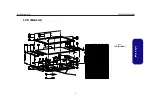
Page 42: ...A Part Lists Bottom Model A Figure 2 Bottom Model A 藍灰色 無鉛 TECHNICAL SERVICE MANUAL Prestigio Nobile 158W 4 ...

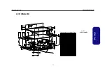
Page 43: ...A Part Lists LCD Model A Figure 3 LCD Model A TECHNICAL SERVICE MANUAL Prestigio Nobile 158W 5 ...

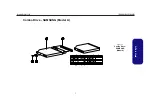
Page 44: ...A Part Lists CD ROM Drive SAMSUNG Model A Figure 4 CD ROM Drive SAMSUNG Model A TECHNICAL SERVICE MANUAL Prestigio Nobile 158W 6 ...

Page 45: ...A Part Lists Combo Drive SAMSUNG Model A Figure 5 Combo Drive SAMSUNG Model A TECHNICAL SERVICE MANUAL Prestigio Nobile 158W 7 ...

Page 46: ...A Part Lists DVD Dual Drive PIONEER Model A Figure 6 DVD Dual Drive PIONEER Model A TECHNICAL SERVICE MANUAL Prestigio Nobile 158W 8 ...

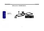
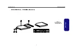
Page 47: ...A Part Lists DVD ROM Drive TOSHIBA Model A Figure 7 DVD ROM Drive TOSHIBA Model A TECHNICAL SERVICE MANUAL Prestigio Nobile 158W 9 ...

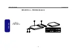
Page 48: ...A Part Lists DVD RW Drive TOSHIBA Model A Figure 8 DVD RW Drive TOSHIBA Model A TECHNICAL SERVICE MANUAL Prestigio Nobile 158W 10 ...

Page 49: ...A Part Lists Top Model B Figure 1 Top Model B TECHNICAL SERVICE MANUAL Prestigio Nobile 158W 11 ...

Page 50: ...A Part Lists Bottom Model B Figure 2 Bottom Model B 銀黑色 無鉛 TECHNICAL SERVICE MANUAL Prestigio Nobile 158W 12 ...

Page 51: ...A Part Lists LCD Model B Figure 3 LCD Model B TECHNICAL SERVICE MANUAL Prestigio Nobile 158W 13 ...

Page 52: ...A Part Lists CD ROM Drive SAMSUNG Model B Figure 4 CD ROM Drive SAMSUNG Model B TECHNICAL SERVICE MANUAL Prestigio Nobile 158W 14 ...

Page 53: ...A Part Lists Combo Drive TEAC Model B Figure 5 Combo Drive TEAC Model B TECHNICAL SERVICE MANUAL Prestigio Nobile 158W 15 ...

Page 54: ...A Part Lists DVD Dual Drive PIONEER Model B Figure 6 DVD Dual Drive PIONEER Model B TECHNICAL SERVICE MANUAL Prestigio Nobile 158W 16 ...

Page 55: ...C202 Page B 21 2 5VS 1 25VS 5VS 3VS Page B 35 DDRAM Page B 8 PCMCIA PCI1620 Page B 22 Charger Page B 36 DDR Termination Page B 9 PCMCIA Socket Page B 23 SMSC LPC47N217 LPC I F Page B 37 Clock Generator Page B 10 TI1394 TSB43AB21 Page B 24 Click Board Page B 38 ICH4 1 1 of 3 Page B 11 M11 AGP PCI Power Page B 25 Hot Key Page B 39 ICH4 2 2 of 3 Page B 12 M10 MEM I F A Page B 26 USB COM1 Page B 40 IC...

Page 56: ...CORE POEWR VCORE ACIN POWER BUTTON CLOCK GEN USB2 0 CD ROM DVD CD RW 50 Pin SYSTEM FWH BIOS LPC BUS NS87383 PCI 1 PCI 2 PCI 3 Charger DC DC DDR VR KB CTRL H8 TOUCH PAD CONN BATTERY TEMP SENSOR CPU FAN 33MHz ATA 100 479 uFCPGA PG3 4 CCD TV OUT USB3 Odem INTEL855PM MCH 593 uFCBGA LCD CONN LVDS CRT OUT LVDS ATI MOBILITY M10 INTEL ICH4 M 421 mBGA MINI PCI ICS950812 TSSOP 40 Pin 1394 VCCP 1 05V 1 2VS 4...

Page 57: ...N3904 B E C RP128 8P4RX2 2K 8 1 7 2 6 5 3 4 ADDR GROUP0 ADDR GROUP1 CLK THERM ITP CONTROL U35A Banias CPU R2 P3 T2 P1 T1 P4 U4 V3 R3 V2 W1 T4 W2 Y4 Y1 U1 AA3 Y3 AA2 U3 AF4 AC4 AC7 AC3 AD3 AE4 AD2 AB4 AC6 AD5 AE2 AD6 AF3 AE1 AF1 AE5 C2 D3 A3 C6 D1 D4 B4 N2 L1 J3 L4 H2 M2 N4 A4 B5 J2 B11 H1 K1 L2 M3 K3 K4 C8 B8 A9 C9 A10 B10 A13 C12 A12 C11 B13 A7 B17 B18 A18 C17 B15 B14 A16 A15 REQ0 REQ1 REQ2 REQ3 ...

Page 58: ...173 VSS174 VSS175 VSS176 VSS177 VSS178 VSS179 VSS180 VSS181 VSS182 VSS183 VSS184 VSS185 VSS186 VSS187 VSS188 VSS189 VSS190 VSS191 R317 0 0805 R315 0 0805 C46 10U 10V 1206 C102 10U 10V 1206 C480 10U 10V 1206 C488 10U 10V 1206 C101 10U 10V 1206 C538 10U 10V 1206 C51 10U 10V 1206 C42 10U 10V 1206 POWER U35C Banias CPU D6 D8 D18 D20 D22 E5 E7 E9 E17 E19 E21 F6 F8 F18 F20 F22 G5 G21 H6 H22 J5 J21 K22 U...

Page 59: ...5 Z0506 Z0508 Z0507 Z0509 Z0510 Z0511 Z0512 Z0513 R341 1K 0402 1 R336 0 0402 C515 1u 0402 C473 1u 0402 R345 4 7K 0402 T T R354 4 7K 0402 C517 10PF DDR SYSTEM MEMORY UB1E I855PM G28 F27 C28 E28 H25 G27 F25 B28 E27 C27 B25 C25 B27 D27 D26 E25 D24 E23 C22 E21 C24 B23 D22 B21 C21 D20 C19 D18 C20 E19 C18 E17 E13 C12 B11 C10 B13 C13 C11 D10 E10 C9 D8 E8 E11 B9 B7 C7 C6 D6 D4 B3 E6 B5 C4 E4 C3 D3 F4 F3 B...

Page 60: ...E11 AC16 AD5 AG5 AH9 AE17 AB16 AB12 AA9 M7 P8 AD15 P25 P24 N27 P23 M26 M25 L28 L27 M27 N28 M24 N24 N25 P27 P26 AA2 AB5 AA5 AB3 AB4 AC5 AA3 AA6 AE3 AB7 AE5 AF3 AC6 AC3 AF4 AE2 AG4 AG2 AE7 AE8 AH2 AC7 AG3 AD7 AH7 AE6 AC8 AG8 AG7 AH3 AF8 AH5 AC11 AC12 AE9 AC10 AE10 AD9 AG9 AC9 AE12 AF10 AG11 AG10 AH11 AG12 AE13 AF12 AG13 AH13 AC14 AF14 AG14 AE14 AG15 AG16 AG17 AH15 AC17 AF16 AE15 AH17 AD17 AE16 U7 V4...

Page 61: ...11 D9 H9 AB9 AD10 AF9 AJ9 A7 F8 J7 L8 N8 R8 U8 W8 AA8 AD8 AF7 AJ7 D5 F6 H6 K6 M6 P6 T6 V6 Y6 AB6 AD6 AF5 AJ5 A3 J4 L4 N4 R4 U4 W4 AA4 AC4 AE4 AJ3 E1 J1 L1 N1 R1 U1 W1 AA1 AC1 AE1 AG1 F12 VSS0 VSS1 VSS2 VSS3 VSS4 VSS5 VSS6 VSS7 VSS8 VSS9 VSS10 VSS11 VSS12 VSS13 VSS14 VSS15 VSS16 VSS17 VSS18 VSS19 VSS20 VSS21 VSS22 VSS23 VSS24 VSS25 VSS26 VSS27 VSS28 VSS29 VSS30 VSS31 VSS32 VSS33 VSS34 VSS35 VSS36 V...

Page 62: ... 108 107 106 105 102 101 115 100 99 117 116 5 7 13 17 6 8 14 18 19 23 29 31 20 24 30 32 41 43 49 53 42 44 50 54 55 59 65 67 56 60 66 68 127 129 135 139 128 130 136 140 141 145 151 153 142 146 152 154 163 165 171 175 164 166 172 176 177 181 187 189 178 182 188 190 9 10 21 22 33 34 36 45 46 57 58 69 70 81 82 92 93 94 113 114 131 132 143 144 155 156 157 167 168 179 180 191 192 3 4 15 16 27 28 38 39 4...

Page 63: ... M_DATA_R_44 M_DATA45 M_DATA_R_4 M_DATA_R_6 M_DQS_R0 M_DATA_R_5 M_DATA_R_14 M_DATA_R_13 M_DATA_R_12 M_DATA_R_7 M_CB_R0 M_DATA_R_36 M_DATA_R_27 M_DATA_R_26 M_DQS_R8 M_CB_R3 M_AA1 M_AA9 M_DATA_R_37 M_CB_R2 M_AA7 M_CB_R1 M_AA12 M_AA8 M_DATA_R_0 M_AA2 M_DQS_R7 M_DATA_R_62 M_AA6 M_AA11 M_DATA_R_3 M_DATA_R_2 M_DATA_R_63 M_AA0 M_DATA_R_1 M_AA4 M_DATA_R_59 M_DATA_R_56 M_DATA_R_58 M_DATA_R_57 M_CB_R6 M_DAT...

Page 64: ...49 9_1 R58 1M Y1 14 318MHz 1 2 C597 5PF C584 5PF R42 49 9_1 U4 ICS950812 TSSOP 4 9 15 20 27 31 36 41 47 46 53 1 8 14 19 32 26 28 23 24 49 56 10 11 12 13 16 17 18 54 55 5 29 39 38 25 33 35 21 22 34 42 45 48 51 44 40 50 52 7 30 2 6 43 3 37 GND GND GND GND GND GND GND GND GND VDDCPU CPU_STOP VDDREF VDDPCI VDDPCI VDD3V66 VDD3V66 VDDA VTT_PWRGD 3V66_4 66MHz_OUT2 3V66_5 66MHz_IN CPUCLKT1 REF PCICLK0 PCI...

Page 65: ...2 10K 0402 R443 150 0402 1 C348 1u 0402 Q15 BSS138 G D S R214 10K 0402 R199 10K 0402 C345 10U 0805 6 3V C711 1u 0402 R213 0 0402 ICH4 M PART A PCI I F CPU I F HUB I F INTERRUPT I F EEPROM LAN I F System Manamement I F UB2A ICH4 M H5 J3 H3 K1 G5 J4 H4 J5 K2 G2 L1 G4 L2 H2 L3 F5 F4 N1 E5 N2 E3 N3 E4 M5 E2 P1 E1 P2 D3 R1 D2 P4 J2 K4 M4 N4 C1 E6 A7 B7 D6 B1 A2 B3 C7 B6 P5 M3 F1 B5 A6 E8 C5 L5 G1 L4 M2...

Page 66: ...K 0402 R176 33 0402 T R223 0 0402 R438 56 0402 RP122 8P4RX10K 8 1 7 2 6 5 3 4 R245 68 R414 1K 0402 R488 0 0402 R156 10K 0402 R174 10K 0402 R475 10K 0402 R177 1K 0402 R169 5 6K R415 22 0402 R130 10K 0402 R480 10K 0402 R477 10K 0402 U30 TC7SZ08 1 2 4 5 3 U12 TC7SZ08 1 2 4 5 3 R121 100K 0402 Y2 32 768KHZ 1 3 2 4 C707 12PF R117 2K_1 ICH4 M PART B Power Management IST AC 97 I F LPC I F USB I F GPIO Unm...

Page 67: ..._0 VCCSUS1 5_1 VCCSUS1 5_2 VCCSUS1 5_3 VCCSUS1 5_4 VCCSUS1 5_5 VCCSUS1 5_6 VCCSUS1 5_7 VCCLAN1 5_0 VCCLAN1 5_1 VCCLAN3 3_0 VCCLAN3 3_1 VCC5REF1 VCC5REF2 VCC5REFSUS1 VCCHI_0 VCCHI_1 VCCHI_2 VCCHI_3 VCCPLL VCC_CPU_IO_0 VCC_CPU_IO_1 VCC_CPU_IO_2 VCC3 3_0 VCC3 3_1 VCC3 3_2 VCC3 3_3 VCC3 3_4 VCC3 3_5 VCC3 3_6 VCC3 3_7 VCC3 3_8 VCC3 3_9 VCC3 3_10 VCC3 3_11 VCC3 3_12 VCC3 3_13 VCC3 3_14 VCC3 3_15 VCC1 5_...

Page 68: ... C307 1u 0402 R461 470K R466 560K R445 0 0402 R448 0 0402 C739 1u 0402 C736 100U 16V JUSB2 USB_4P 1 2 3 4 GND1 GND2 GND3 GND4 VCC DATA DATA GND S S S S L41 L_0805 159 1 2 L43 L_0805 159 1 2 L76 PLW3216S_161T 1 4 2 3 R449 0 0402 R446 0 0402 L71 PLW3216S_161T 1 4 2 3 C694 100U 16V C303 1u 0402 JUSB1 USB_4P 1 2 3 4 GND1 GND2 GND3 GND4 VCC DATA DATA GND S S S S CLOSE WITH HOST CLOSE WITH HOST 1A 1A 80...

Page 69: ...BE1 PCI_AD16 PCI_AD7 PCI_AD 15 0 PCI_AD 31 16 Z1521 Z1522 Z1523 Z1525 Z1524 Z1526 Z1527 Z1528 Z1529 Z1530 Z1532 Z1533 Z1534 Z1535 Z1537 Z1536 Z1538 Z1539 Z1540 Z1541 Z1542 Z1543 Z1544 Z1545 Z1546 Z1547 Z1548 Z1549 Z1554 Z1556 Z1559 Z1555 Z1558 Z1557 Z1553 Z1552 Z1551 Z1531 Z1520 Z1519 Z1518 Z1517 Z1516 Z1515 Z1514 Z1511 Z1550 WL_DE 3V USB_PP4 USB_PN4 5V CCDVCC PCI_AD17 C813 4 7U 0805 6 3V JCCD1 CC...

Page 70: ..._SDD 0 15 IDE_SDD8 Z1605 IDE_PDD7 IDE_PDCS1 IDE_PDCS3 IDE_PDD9 IDE_PDA2 IDE_PDA1 IDE_PDIOR IDE_PDDREQ IDE_PDD8 IDE_PDD12 IDE_PDD0 IDE_PDD15 Z1601 IDE_PDD6 IDE_PDIOW IDE_PDD3 PDLED IDE_PDD4 IDE_PDD13 IDE_PDD5 IDE_PIORDY IDE_PDD14 INT_IRQ14 IDE_PDDACK IDE_PDD 0 15 P66CBLID PCIRST IDE_PDD11 IDE_PDD10 IDE_PDD2 IDE_PDD1 IDE_PDA0 PCIRST Z1608 R259 33 0402 C335 1u 0402 JHDD1 CON44 1 3 5 7 9 11 13 15 17 1...

Page 71: ...56 57 58 59 60 61 62 63 64 65 66 67 68 69 70 71 72 73 74 75 76 77 78 79 80 81 82 83 84 85 86 87 88 89 90 91 92 93 94 95 96 97 98 99 100 101 102 103 104 105 106 107 108 109 110 111 112 113 114 115 116 117 118 119 120 123 124 125 126 121 122 127 128 MDI0 MDI0 AVDDL VSS MDI1 MDI1 AVDDL CTRL25 VSS AVDDH HSDAC HSDAC VSS MDI2 MDI2 AVDDL VSS MDI3 MDI3 AVDDL VSSPST GND ISOLATEB VDD18 INTAB VDD33 RSTB CLK ...

Page 72: ...12 1u 0402 L91 PLW3216S_161T 1 4 2 3 C258 470U 6 3V JA1 SHORT A 1 2 R269 4 7K 0402 L92 PLW3216S_161T 1 4 2 3 R264 2 2K 0402 RP126 10P8RX4 7K 1 2 3 4 5 10 6 7 8 9 RN7 8P4RX18 1 8 2 7 3 6 4 5 C783 0 047u L88 L_0805 159 0603 C321 1u 0402 C756 1000PF 0402 R514 47K C418 1u 0402 U19 74AHC1G14 2 4 5 3 1 CN6 CON 26P 1 2 3 4 5 6 7 8 9 10 11 12 13 14 15 16 17 18 19 20 22 23 25 24 21 26 R273 10K 0402 R261 2 ...

Page 73: ...ST SLP_S3 SUSB I855PM ODEM PCIRST DDON SUSC SUSC SUSC 1 5VS 1 5V AD20 D 1 1394 INTERRUPTS 3 AD18 A B AD16 PCI DEVICE PCICLK AD25 0 PCMCIA PIN11 C IDSEL PIN17 2 PIN16 PIN10 GIGA LAN MINI PCI REQ GNT ICHPWROK 35 7ms CLKEN 20ms V_CORE DELAY_PG_VGATE PM_RSMRST 4ms 236 2ms 3 8ms 3V 6ms 1 5V 2 5V 1 5VS 60us PCIRST 3ms 1ms 1ms H_PWRGD H_RCIN PWR_BTN 1 3ms 10ms SUSB 36ms 5V 0 7ms 1ms 1 2VS H_CPURST 4ms PC...

Page 74: ... 1N4148 A C R541 10K 0402 L18 0 0402 L17 0 0402 R60 10K 0402 R148 1K 0402 T393 T T Q14 2N7002 G S D R150 10K 0402 T392 T T391 T R116 18 0805 D34 RB751V A C R126 10K 0402 JFAN1 CPU_CON3 1 2 3 T388 T R196 1M L2 L_0805 159 1 2 CN5 H8_DEBUG PCB Footprint SPUFZ 10B 1 2 3 4 5 6 7 8 9 10 R125 10K 0402 L32 L_0805 159 1 2 R182 2 2K 0402 C6 0 1U 0805 25V R183 2 2K 0402 R185 100K 0402 R189 10K 0402 C3 10U 08...

Page 75: ...K 0402 C382 1u 0402 C403 1u 0402 C805 4 7U 0805 C374 1u R554 20K R267 1 5K 0402 R258 1 5K 0402 R257 1 5K 0402 C405 1u PQ66 4800 4 6 2 5 7 3 1 8 C411 1u C779 1u 0402 R532 51K R499 0 0402 C397 4 7U 0805 C410 1u C406 1u R496 20K C746 1u R276 10K 0402 R555 20K R531 23 7K R508 0 0402 C398 1u 0402 R275 10K 0402 C394 1u C393 1u R265 1 5K 0402 R266 1 5K 0402 C422 1u 0402 C427 1u 0402 C781 1u 0402 C765 100...

Page 76: ...D_VSS1 SD_VDD SD_CLK SD_VSS2 SD_DAT0 SD_DAT1 SD_DAT2 SD_WP SD_CD GND4 GND3 GND2 GND1 R222 0 0402 R271 43K R234 47 R544 0 PCI1620 PCI1620 U44 G2 G3 H6 F1 G5 F2 F3 E2 F5 E3 D1 B12 A4 C5 E6 B5 C8 B8 A8 E9 F9 C9 B9 F10 B10 F12 F11 E11 B11 A11 C12 E12 G6 F6 F8 B14 A5 F7 E8 B13 A13 E10 B7 C7 E7 C6 B6 C10 C13 D19 E13 A7 A12 G1 G19 J19 N1 N19 R1 P19 W8 W13 A6 A9 A14 E1 F19 K1 P1 R19 F14 C15 H17 N14 U11 G1...

Page 77: ... 32 33 34 69 70 71 72 74 73 35 36 37 38 39 40 41 42 43 44 45 46 47 48 49 50 51 52 53 54 55 56 57 58 59 60 61 62 63 64 65 66 67 68 GND D3 CAD0 D4 CAD1 D5 CAD3 D6 CAD5 D7 CAD7 CE1 CCBE0 A10 CAD9 OE CAD11 A11 CAD12 A9 CAD14 A8 CCBE1 A13 CPAR A14 CPERR WE PGM CGNT RDY BSY IRQ INT VCC VPP1 A16 CCLK A15 CIRDY A12 CCBE2 A7 CAD18 A6 CAD20 A5 CAD21 A4 CAD22 A3 CAD23 A2 CAD24 A1 CAD25 A0 CAD26 D0 CAD27 D1 C...

Page 78: ... 1u 0402 C748 1u 0402 C747 1u 0402 C749 1u 0402 C402 1u 0402 Y4 24 576MHz 1 2 RP174 8P4RX220 8 1 7 2 6 5 3 4 C386 12PF TSB43AB21 POWER CLASS OSCILLATOR PHY PORT 2 BIAS CURRENT FILTER PHY PORT 1 EEPROM 2 WIRE BUS PCI BUS INTERFACE U28 TSB43AB21 13 16 18 19 21 22 24 25 26 28 29 31 32 36 37 38 40 41 42 43 45 46 49 50 52 53 54 56 84 82 81 80 79 77 76 74 71 70 69 67 66 65 63 61 58 57 106 125 124 123 12...

Page 79: ...2 0 0402 C213 10U 0805 6 3V C212 1u 0402 R112 1K 0402 1 L11 HCB1608K 121T25 1 2 R385 0 0402 M9 X INNER ROWS Part 7 of 7 UB4G M11 P M9 X_M10P_0 J10 J12 J14 J15 J19 J16 J17 J21 K9 P22 M9 R22 T9 P9 U9 R9 T22 M22 K22 U22 V9 V22 Y9 Y22 AB9 AB22 J9 J11 J13 J18 J20 J22 L9 L22 N9 N22 W9 W22 AA9 AA22 VDDC VDDC VDDC VDDC VDDC VDDC VDDC VDDC VDDC VDDC VDDC VDDC VDDC VDDC VDDC VDDC VDDC VDDC VDDC VDDC VDDC VD...

Page 80: ...EM_MD36 MEMA_MD37 MEMA_MD36 VAMEM_MD38 VAMEM_MD39 MEMA_MD38 MEMA_MD39 VQSA6 VDQMA 6 MEMA_DQM 6 MEMA_QS6 VAMEM_MD50 VAMEM_MD51 MEMA_MD51 MEMA_MD50 VAMEM_MD48 VAMEM_MD49 MEMA_MD49 MEMA_MD48 VAMEM_MD53 VAMEM_MD52 VAMEM_MD55 VAMEM_MD54 MEMA_MD52 MEMA_MD55 MEMA_MD53 MEMA_MD54 VAMEM_MD56 VAMEM_MD58 MEMA_MD58 MEMA_MD56 VAMEM_MD57 MEMA_MD57 VQSA7 VDQMA 7 MEMA_QS7 MEMA_DQM 7 Z2601 RP92 8P4RX10 0402 8 1 7 2...

Page 81: ...43 VQSB5 VDQMB 5 MEMB_MD42 MEMB_MD43 MEMB_QS5 MEMB_DQM 5 MEMB_MD38 MEMB_MD41 MEMB_MD40 MEMB_MD39 VBMEM_MD40 VBMEM_MD41 VBMEM_MD38 VBMEM_MD39 VBMEM_MD61 VBMEM_MD60 MEMB_MD61 MEMB_MD60 MEMB_MD62 MEMB_MD63 VDQMB 7 MEMB_DQM 7 MEMB_QS7 VQSB7 VBMEM_MD58 VBMEM_MD59 MEMB_MD58 MEMB_MD59 MEMB_MD56 MEMB_MD54 MEMB_MD55 MEMB_MD57 VBMEM_MD57 VBMEM_MD56 VBMEM_MD55 VBMEM_MD54 VBMEM_MD62 VBMEM_MD63 MEMB_QS6 MEMB_M...

Page 82: ...O0 VDDA VDD SS_ENA CLKOUT GND VDDO1 VDDREF T U34D 74HCT125 12 11 14 13 7 C122 68PF R432 75 0402 C458 1u 0402 C123 68PF U34B 74HCT125 5 6 14 4 7 C262 10U 0805 6 3V Q21 2N7002 G D S U34A 74HCT125 2 3 14 1 7 R17 4 7K 0402 R408 22 0402 C63 220PF D48 BAV99 C AC A C57 220PF D47 BAV99 C AC A R431 150 0402 C481 1000PF 0402 D52 BAV99 C AC A D51 BAV99 C AC A JVGA1 VGA DSUB 8 7 6 5 4 3 2 1 9 10 11 12 13 14 1...

Page 83: ...DS_TXU2P LVDS_TXU1P LVDS_TXU1N LVDS_TXLCKP LVDS_TXLCKN LVDS_TXL1P LVDS_TXL1N LVDS_TXL0P LVDS_TXU0P LVDS_TXU0N LVDS_TXL2N LVDS_TXL2P C557 4 7U 0805 R546 4 7K R364 1K 0402 JLCD1 CON30 GND1 GND2 GND3 GND4 1 2 3 4 5 6 7 8 9 10 11 12 13 14 15 16 17 18 19 20 21 22 23 24 25 26 27 28 29 30 GND GND GND GND C553 1u 0402 C562 1000PF 0402 L57 L_1206 1 2 R547 4 7K U36 MIC2505 1 6 5 4 8 2 3 7 CTL OUT IN GATE OU...

Page 84: ...CAS 27 MEMB_QS2 27 MEMB_MD29 27 MEMB_DQM 2 27 MEMB_MD20 27 MEMB_MD17 27 MEMB_MD23 27 MEMB_MD19 27 MEMB_MD21 27 MEMB_MD1 27 MEMB_MD18 27 MEMB_MD3 27 MEMB_QS0 27 MEMB_MD4 27 MEMB_MD6 27 MEMB_MD5 27 MEMB_DQM 0 27 1 25VS 2 5VS RP147 8P4RX56 0402 8 1 7 2 6 5 3 4 RP68 8P4RX56 0402 8 1 7 2 6 5 3 4 RP75 8P4RX56 0402 8 1 7 2 6 5 3 4 RP132 8P4RX56 0402 8 1 7 2 6 5 3 4 RP77 8P4RX56 0402 8 1 7 2 6 5 3 4 RP88 ...

Page 85: ...Z3125 Z3102 Z3101 HDD_LED 5VS 3VH8 3VS INTMIC AUDVDD Z3127 3V TPADDATA TPADCLK R537 75 0402 R536 2 2K 0402 C142 4 7U 0805 C785 1U 0805 C784 1U 0805 T C786 1u D4 F01J2E A C C556 1u 0402 JTP1 CON4_TP 1 2 3 4 R27 10K 0402 D5 F01J2E A C T C787 680PF T C416 680PF R53 10K 0402 T C414 680PF L49 L_0603 164 C803 22U 1206 T C424 680PF R326 220 0805 T C426 680PF CN2 CON12 1 2 3 4 5 6 7 8 9 10 11 12 R293 0 04...

Page 86: ...1 SENSE1 SENSE1 PLLIN VIN VOSENSE1 PLLFLTR ITH1 FCB 3 3VOUT SGND INTVCC BOOST2 TG2 SW2 BG2 SENSE2 SENSE2 VOSENSE2 ITH2 EXTVCC RUN SS1 RUN SS2 PGOOD PGND NC NC NC NC PC69 220U 4V D PC67 220U 4V D PQ39 2N7002 G S D Q5 BSS138 G D S PQ38 2N7002 G D S PR56 17 8K_1 PC162 100PF PC155 220U 4V D PR162 100K PD19 RB751V A C PC79 1000PF R124 100K 0402 R89 0 0402 R88 0 0402 PR57 0 PR54 0 0402 Q8 2N7002 G S D P...

Page 87: ... 10 PQ33 AO4408 4 6 2 7 3 8 5 1 PR125 1M PR41 0 PC126 220U 4V D PR124 1M PR114 10 PR32 0 PR33 10K PR129 1 3M PC47 470PF PC50 1u 0402 PC58 10U 35V 1210 PQ36 2N7002 G S D PR131 0 PR47 0 PR147 2 2K PC59 220U 4V D PR156 0 PR127 499K_1 PC18 1u 0402 PD33 RB751V A C PQ29 IRF7831 4 6 2 7 3 8 5 1 PC135 3300PF PQ67 IRF7831 4 6 2 7 3 8 5 1 PC42 4 7U 0805 PR141 22 PR128 12 7K_1 PR123 43 2K_1 PQ58 2N3904 B E C...

Page 88: ...ENSE1 SENSE1 PLLIN VIN VOSENSE1 PLLFLTR ITH1 FCB 3 3VOUT SGND INTVCC BOOST2 TG2 SW2 BG2 SENSE2 SENSE2 VOSENSE2 ITH2 EXTVCC RUN SS1 RUN SS2 PGOOD PGND NC NC NC NC PR116 0 PQ7 2N7002 G D S PC38 01u PC36 33PF PR121 10 0805 PZD1 5 1V A C PC28 1u 0402 PR120 15K PR12 100K PC33 1000PF PR110 10 0805 PQ52 2N7002 G S D PC29 1u 0402 PR22 10 0805 PQ47 2N7002 G S D PR109 105K_1 PQ13 AO4900 1 2 5 6 7 8 3 4 S2 G...

Page 89: ...4V D PR90 15m 1206 1 H7 MTH315D178 2 3 4 5 6 7 8 9 1 H20 MTH315D111 2 3 4 5 6 7 8 9 PC103 2200PF 1 H3 MTH315D111 2 3 4 5 6 7 8 9 1 H26 MTH315D111 2 3 4 5 6 7 8 9 PR6 0 PD28 RB751V A C PC16 1u PR94 0 PC22 01u 1 H9 MTH237D110 2 3 4 5 6 7 8 9 PC111 33PF 1 H6 MTH315D162 2 3 4 5 6 7 8 9 PR9 2K PQ45 2N7002 G S D 1 H2 MTH315D111 2 3 4 5 6 7 8 9 1 H12 MTH315D111 2 3 4 5 6 7 8 9 PR86 5m 2010 PC19 10U 35V 1...

Page 90: ... A C PQ1 AO4407 4 6 2 5 7 3 1 8 PD2 1SS355 A C PC95 1U 0805 PQ27 DTA114EUA C E B PD3 1SS355 A C PR44 30K_1 PD7 F1AJ4 A C PC142 10U 35V 1210 PR72 10K PQ26 DTC114EUA C E B PC87 0 1U 0805 25V CN1 CON7 1 2 3 4 6 5 7 PC81 1U 0805 PC5 1u 0402 PD5 1SS355 A C PR1 330 PC3 30PF PL1 CDRH 1205 470 PC62 10U 35V 1210 PC96 10U 25V_DIP PR81 5 1 PC9 0 1U 0805 25V PR43 6 8K_1 PC15 10U 35V 1210 PC8 1u 0402 PC11 10U ...

Page 91: ... Z3707 Z3708 Z3705 Z3706 LPC_FRAME CLKRUN INT_SERIRQ RP124 8P4RX10K 8 1 7 2 6 5 3 4 R246 1K 0402 R249 1K 0402 R202 10K 0402 R243 100K 0402 RP120 8P4RX10K 8 1 7 2 6 5 3 4 COM LPT IR LPC GPIO PORT POWER U27 LPC47N217 32 23 6 33 37 38 8 48 29 26 39 24 25 61 49 63 15 40 27 16 31 55 56 57 19 58 18 53 22 45 20 51 44 46 35 12 54 43 47 10 17 21 50 28 30 34 36 13 14 59 42 41 60 9 5 64 62 1 2 11 7 3 4 52 GP...

Page 92: ...H5 C55D55 CJ2 CON1 1 2 3 4 1 2 3 4 CH6 C55D55 1 CH4 MTH237D91 2 3 4 5 6 7 8 9 1 CH3 MTH237D91 2 3 4 5 6 7 8 9 CH1 C237D91 CM1 M MARK1 CJ1 CON2 1 2 3 4 5 6 7 8 9 10 11 12 1 2 3 4 5 6 7 8 9 10 11 12 CM4 M MARK1 CM3 M MARK1 CM2 M MARK1 CH2 C237D91 CM5 M MARK1 CM6 M MARK1 SW4 HCH STS 05 3 1 4 2 5 6 SW1 HCH STS 05 3 1 4 2 5 6 CLICK BOARD Synaptics Touch Pad 12 pin connector VENDOR PART NUMBER TM41P 351...

Page 93: ...WEB0 1 HH1 MTH237D91 2 3 4 5 6 7 8 9 1 HH2 MTH237D91 2 3 4 5 6 7 8 9 1 HH3 MTH237D91 2 3 4 5 6 7 8 9 1 HH4 MTH237D91 2 3 4 5 6 7 8 9 HSW1 HCH STS 02 3 1 4 2 HSW3 HCH STS 02 3 1 4 2 JHOT1 CON4 1 2 3 4 1 2 3 4 HSW2 HCH STS 02 3 1 4 2 Sheet 38 of 40 Hot Key TECHNICAL SERVICE MANUAL Prestigio Nobile 158W 39 ...

Page 94: ...N T2IN T3IN R2OUTB R1OUT R2OUT R3OUT R4OUT R5OUT FORCEON FORCEOFF INVALID V V T1OUT T2OUT T3OUT R1IN R2IN R3IN R4IN R5IN GND VCC CC8 1u CR2 470K CD1 1SS355 A C UH3 H6_0D2_8 CL1 FCM2012V 121 1 2 CC13 1u 0603 CR4 100K CCN1 CON 26P 1 2 3 4 5 6 7 8 9 10 11 12 13 14 15 16 17 18 19 20 22 23 25 24 21 26 CL2 PLW3216S_161T 1 4 2 3 CC7 1u T CC1 10U 10V 1206 CCP2 8P4C 120P 1 8 2 7 3 6 4 5 CC12 1u 0603 CJCOM1...

Page 95: ... 1 8 4 MH6 HOLE1_2 MR9 100m 2512 MH4 H6_0D2_8 MD3 LED A C MC125 0 1U 0805 25V MD1 LED A C MR44 100K_1 MD2 LED A C MR43 10K_1 MR127 100K MR41 10K_1 MH2 H6_0D2_8 10K 10K MQ1 DTC114EUA C B E MC119 0 1U 0805 25V MC149 1U 0805 100K MR2 MH5 HOLE1_2 1K MR4 MH1 H6_0D2_8 MCN12 CON7_M 1 2 3 4 6 5 7 MC1008 0 1U 0805 25V MC2 0 1U 0805 25V MC910 1u MSW2 TJ G 5 3 1 4 2 5 6 MSW1 HCH 00HEB12 1 3 2 MC118 0 1U 0805...

Page 96: ...www prestigio com ...

Reviews: