background image


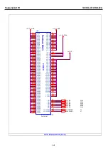
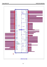
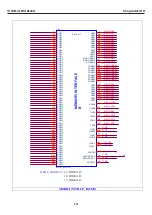
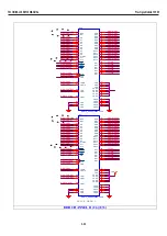
ICH4-M 1/3

PCI
I/F

S

y

s

te

m

M

a

n

a

g

e

m

e

n

t

I/

F

Hub  I/F

In

te

rr

u

p

I/

F

L

A

N

 I

/F

CPU I/F

E

E

P

R

O

M

I/

F

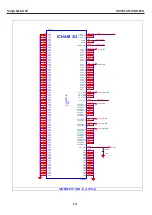
U16A

ICH4-M

H5

J3

H3

K1

G5

J4

H4

J5

K2

G2

L1

G4

L2

H2

L3

F5
F4

N1

E5

N2

E3

N3

E4

M5

E2
P1
E1
P2

D3
R1
D2

P4

J2

K4

M4
N4

C1

E6
A7
B7

D6

B1
A2
B3

C7

B6

P5

M3

F1
B5
A6
E8

C5

L5

G1

L4

M2

W2

U5

K5
F3
F2

Y22
AB23

AA21
W21
V22
AB22
V21
Y23
U22
U21
W23
V23

W6
AC3
AB1
AC4
AB4
AA5

U23

D5
C2
B4
A3

P21

N20

T21

M23

R23

R22

J22

L19
L20
M19
M21
P19
R19
T20
R20
P23
L22
N22
K21

J19
H19
K20

AC13

C4

C3

D7

C8

AA19

B10
C10
A12

A10
A9
A11

C11
B11
Y5

D10

C12

D11
A8

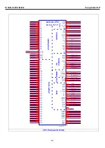
PCI_AD0
PCI_AD1
PCI_AD2
PCI_AD3
PCI_AD4
PCI_AD5
PCI_AD6
PCI_AD7
PCI_AD8
PCI_AD9
PCI_AD10
PCI_AD11
PCI_AD12
PCI_AD13
PCI_AD14
PCI_AD15
PCI_AD16
PCI_AD17
PCI_AD18
PCI_AD19
PCI_AD20
PCI_AD21
PCI_AD22
PCI_AD23
PCI_AD24
PCI_AD25
PCI_AD26
PCI_AD27
PCI_AD28
PCI_AD29
PCI_AD30
PCI_AD31

PCI_CBE0#
PCI_CBE1#
PCI_CBE2#
PCI_CBE3#

PCI_GNT0#
PCI_GNT1#
PCI_GNT2#
PCI_GNT3#
PCI_GNT4#

PCI_REQ0#
PCI_REQ1#
PCI_REQ2#
PCI_REQ3#
PCI_REQ4#

PCI_CLK
PCI_DEVSEL#
PCI_FRAME#
PCI_REQA#/GPIO0
PCI_REQB#/REQ5#/GPIO1
PCI_GNTA#/GPIO16
PCI_GNTB#/GNT5#/GPIO17
PCI_IRDY#
PCI_PAR
PCI_PERR#
PCI_LOCK#
PCI_PME#
PCI_RST#
PCI_SERR#
PCI_STOP#
PCI_TRDY#

CPU_A20GATE

CPU_A20M#

CPU_FERR#

CPU_IGNNE#

CPU_INIT#

CPU_INTR

CPU_NMI

CPU_PWRGD

CPU_RCIN#

CPU_SLP#

CPU_SMI#

CPU_STPCLK#

SM_INTRUDER#

SM_LINK0
SM_LINK1

SMB_CLK

SMB_DATA

SMB_ALERT#/GPIO11

CPU_DPSLP#

INT_PIRQA#
INT_PIRQB#

INT_PIRQC#
INT_PIRQD#

HUB_STB/HUB_STBS

HUB_STB#/HUB_STBF

HUB_CLK

HUB_VREF

HUB_COMP

HUB_VSWING

INT_SERIRQ

HUB_PD0
HUB_PD1
HUB_PD2
HUB_PD3
HUB_PD4
HUB_PD5
HUB_PD6
HUB_PD7
HUB_PD8
HUB_PD9

HUB_PD10
HUB_PD11

INT_APICCLK

INT_APICD0
INT_APICD1

INT_IRQ14

INT_PIRQH#/GPIO5

INT_PIRQG#/GPIO4

INT_PIRQF#/GPIO3

INT_PIRQE#/GPIO2

INT_IRQ15

LAN_TXD0
LAN_TXD1
LAN_TXD2

LAN_RXD0
LAN_RXD1
LAN_RXD2

LAN_CLK

LAN_RSTSYNC

LAN_RST#

EEP_CS

EEP_SHCLK

EEP_DIN

EEP_DOUT

+V3.3


ICH4-M (U16B)


TECHNICAL SERVICE MANUAL

Prestigio Nobile 159W

2-11

Summary of Contents for NOBILE 159W

Page 1: ...PRESTIGIO NOBILE 159W TECHNICAL SERVICE MANUAL ...

Page 2: ......

Page 3: ...2 1 1 Hardware Specification 3 1 2 Software Specification 17 TECHNICALSERVICEMANUAL PrestigioNobile159W 1 2 ...

Page 4: ...novations hlike Micro op Fusion and Advanced Stack Management that reduce the number of micro ops handled by the processor These results in more efficient scheduling and better performance at lower power The on die 32 kB Level 1 instruction and data caches and the 1 MB Level 2 cache with Advanced Transfer Cache Architecture enable significant performance improvement over existing mobile processors...

Page 5: ... Stop Grant Deep Sleep and Deeper Sleep low power states The Intel Pentium M processor utilizes socketable Micro Flip Chip Pin Grid Array Micro FCPGA and surface mount Micro Flip Chip Ball Grid Array Micro FCBGA package technology The Micro FCPGA package plugs into a 479 hole surface mount Zero Insertion Force ZIF socket which is referred to as the mPGA479M socket This document includes specificat...

Page 6: ... driver technology with integrated GTL termination resistors and low voltage operation 1 05 V Support for DPWR signal to Intel Pentium M processor for PSB power management Memory System Directly supports one DDR channel 64b wide 72b with ECC Supports 200 MHz and 266 MHz DDR devices Supports 64 Mb 128 Mb 256 Mb and 512 Mb technologies for x16 devices and x8 devices All supported devices have four b...

Page 7: ...CI semantic FRAME initiated accesses to DRAM are snooped AGP semantic PIPE and SBA accesses to DRAM are not snooped High priority access support Hierarchical PCI configuration mechanism Delayed transaction support for AGP to DRAM FRAME semantic reads that can not be serviced immediately 32 bit upstream address support for inbound AGP and PCI cycles 32 bit downstream address support for outbound PC...

Page 8: ... 2 compliant with support for 33 MHz PCI operations PCI slots supports up to 6 Req Gnt pairs ACPI Power Management Logic Support Enhanced DMA Controller Interrupt Controller and Timer Functions Integrated IDE controller supports Ultra ATA100 66 33 USB host interface with support for 6 USB ports 3 UHCI host controllers 1 EHCI high speed USB 2 0 Host Controller Integrated LAN Controller System Manag...

Page 9: ...Revision 2 2 Specification at 33 MHz Ø 133 MB sec maximum throughput Ø Supports up to 6 master devices on PCI Ø One PCI REQ GNT pair can be given higher arbitration priority intended for external 1394 host controller Ø Support for 44 bit addressing on PCI using DAC protocol Integrated LAN Controller Ø WfM 2 0 and IEEE 802 3 compliant Ø LAN Connect Interface LCI Ø 10 100 Mbit sec ethernet support I...

Page 10: ...decode Ø Supports wake up events Interrupt Controller Ø Support up to 8 PCI interrupt pins Ø Supports PCI 2 2 message signaled interrupts Ø Two cascaded 82C59 with 15 interrupts Ø Integrated I O APIC capability with 24 interrupts Ø Supports serial interrupt protocol Ø Supports processor system bus interrupt delivery New 1 5 V operation with 3 3 V I O Ø 5V tolerant buffers on IDE PCI USB over curre...

Page 11: ...MA collection buffer to provide Type F DMA performance for all DMA channels Real Time Clock Ø 256 byte battery backed CMOS RAM System TCO Reduction Circuits Ø Timers to generate SMI and Reset upon detection of system hang Ø Timers to detect improper processor reset Ø Supports ability to disable external devices SMBus Ø New Hardware packet error checking Ø New Supports SMBus 2 0 Specification Ø Hos...

Page 12: ...requency with resolution up to 0 1 MHz increment Output Features 3 Differential CPU Clock Pairs 3 3V 7 PCI 3 3V 33 3MHz including 2 early PCI clocks 3 PCI_F 3 3V 33 3MHz 1 USB 3 3V 48MHz 1 DOT 3 3V 48MHz 1 REF 3 3V 14 318MHz 5 3V66 3 3V 66 6MHz 1 VCH 3V66 3 3V 48MHz or 66 6MHz Features Benefits Provides standard frequencies and additional 3 5 and 10 over clocked frequencies Supports spread spectru...

Page 13: ... realistic texture and lighting effects than ever before Ø Significant improvement over first generation shaders introduced in DirectX 8 with a much more powerful and intuitive instruction set Ø Offers full support for this feature in OpenGL applications SMOOTHVISION 2 0 Flexible Anti Aliasing and Anisotropic Filtering Ø 2x 4x 6x full scene anti aliasing modes Ø Adaptive algorithm with programmabl...

Page 14: ...ng and decoding Features In Detail 2D Acceleration Features Ø A highly optimized 128 bit engine capable of processing multiple pixels clock Ø Hardware acceleration is provided for Bitblt line drawing polygon and rectangle fills bit masking monochrome expansion panning and scrolling scissoring and full ROP support including ROP3 Ø Optimized handling of fonts and text using ATI proprietary technique...

Page 15: ...s and 256 vectors of constant store This includes Vertex Shader Loops Branches and Subroutines which allow for vertex shader programs of around 64 000 instructions in length Motion Video Acceleration Features Ø Video scaling and fully programmable YCrCb to RGB color space conversion for full screen full speed video playback and fully adjustable color controls Ø Hardware I2C Ø VIP 2 0 with multi ch...

Page 16: ...nterlaced video on non interlaced displays by analyzing image and using optimal de interlacing function on a per pixel basis Dual Display Features General Ø Hydravision for dual monitor support Ø Dual independent displays LCD DVI DVI CRT LCD TV CRT TV etc Ø Two independent CRT controllers to support two asynchronous simultaneous display paths Ø Integrated second DAC for the second CRT TV support Ø...

Page 17: ...ifact suppressed display on a PAL or NTSC TV with Composite S Video and RGB outputs Ø Support for Macrovision 7 02 copy protection standard required by DVD players a fully programmable timing capability it will accommodate potential changes in the Macrovision algorithm without any hardware changes Ø YUV Direct Pass through mode for video MPEG playback and DVD provides the best quality movie playba...

Page 18: ...e and dual pixel per clock up to 230MHz dual channel 115MHz per channel Ø Supports LCD panels up to QXGA 2048x1536 60Hz resolution Ø General purpose I O pins that allows support of LCD panel detection Ø Conformance with OpenLDI and VESA FPDI specifications Ø Common Panel Interface Specification CPIS compliant Ø Ratiometric expansion with improved sharpness for top image quality when scaling up fro...

Page 19: ...er through the use of data inversion signals for both writes and reads Higher clock speeds with no external termination required Power Management Features Ø Single chip solution in 0 13 micron 1 0V 1 2V CMOS technology Ø Full ACPI 1 0b OnNow and IAPC Instantly Available PC power management Ø PCI bus power management 1 1 and AGP Busy and Stop signals Rev 1 61 and Solano 2 M Ø Static and dynamic Pow...

Page 20: ...plies with all relevant sections of the current PC design guide specifications from Intel Microsoft Ø Fully compliant with PC99 PC99a and PC 2001 requirements Ø Fully compliant with Mobile PCI rev 1 0 Ø Bi endian support for compliance on a variety of processor platforms Test Capability Features The MOBILITY M11 has a variety of test modes and capabilities that provide a very high fault coverage a...

Page 21: ...indows XP alpha cursor as well as acceleration of new GDI extensions such as Alpha BLTs Transparent BLTs and Gradient Fills Compliance with Wassenaar Agreement Ø 3D vector rate as defined by the Wassenaar Agreement is 18 23 M 10 pixel vectors sec for all of M11 CSP64 M11 CSP128 F PCMCIA OZ711MC1 Feature Ø Single Slot CardBus Controller Ø Integrated Smart Card Reader SCR Controllers Ø Integrated Fl...

Page 22: ... Version 2 2 Compliant Ø Supports SD Memory Card CPRM Security Mode Power Management Features Ø Auxiliary Power Supply VAUX For D3COLD Standby Ø ACPI PCI Bus Power Management Rev 1 1 Compliant Ø Supports OnNow LAN Wake up Ring Indicate CardBus Wake Signaling via PME and CLKRUN OZ2216 The OZ2216 is a dual slot PCMCIA Personal Computer Memory Card International Association PC Card and CardBus power ...

Page 23: ...ly available input voltage Ø Standby Mode 50 mA Current Limit Typical Ø Current limit and over temperature shutdown Ø 12V supply can be disabled except during 12V Flash memory programming Ø Break before make switching Ø Low on resistance for 5V VCC Ø Low on resistance for 3 3V VCC G IEEE 1394 TSB43AB22A The Texas Instruments TSB43AB22A device is an integrated 1394a 2000 OHCI PHY link layer control...

Page 24: ... node in a cable based 1394 network Each cable port incorporates two differential line transceivers The transceivers include circuitry to monitor the line conditions as needed for determining connection status for initialization and arbitration and for packet reception and transmission The TSB43AB22A PHY layer requires only an external 24 576 MHz crystal as a reference for the cable ports An exter...

Page 25: ...ence of an active connection This bias voltage source must be stabilized by an external filter capacitor of 1 0 μF The line drivers in the TSB43AB22A device operate in a high impedance current mode and are designed to work with external 112 Ω line termination resistor networks in order to match the 110 Ω cable impedance One network is provided at each end of a twisted pair cable Each network is co...

Page 26: ... TSB43AB22A device supports hardware enhancements to better support digital video DV and MPEG data stream reception and transmission These enhancements are enabled through the isochronous receive digital video enhancements register at OHCI offset A88h see Chapter 5 TI Extension Registers The enhancements include automatic timestamp insertion for transmitted DV and MPEG formatted streams and common...

Page 27: ...acy DV components PHY Link logic performs system initialization and arbitration functions PHY Link encode and decode functions included for data strobe bit level encoding PHY Link incoming data resynchronized to local clock Low cost 24 576 MHz crystal provides transmit and receive data at 100M bits s 200M bits s and 400M bits s Node power class information signaling for system power management Ser...

Page 28: ...to Power down that is the analog part of the RTL8100C L can be shut down temporarily according to user requirements or when the RTL8100C L is in a power down state with the wakeup function disabled In addition when the analog part is shut down and the IsolateB pin is low i e the main power is off then both the analog and digital parts stop functioning and the power consumption of the RTL8100C L wi...

Page 29: ...d Microsoft wake up frame Ø Supports 4 Wake On LAN WOL signals active high active low positive pulse and negative pulse Ø Supports auxiliary power on internal reset to be ready for remote wake up when main power still remains off Ø Supports auxiliary power auto detect and sets the related capability of power management registers in PCI configuration space Ø Includes a programmable PCI burst size a...

Page 30: ...table personal computers multimedia subsystems However it is suitable for any audio subsystem requiring stereo audio input output with S PDIF digital output at competitive prices Feature Ø AC 97 2 2 S PDIF extension compliant codec Ø 18 bit stereo full duplex SD codec Ø 1Hz resolution VSR Variable Sampling Rate Ø Integrated IEC958 line driver for S PDIF Ø S PDIF compressed digital or LPCM audio ou...

Page 31: ...m 40 dB to 20 dB Ø Fade Mode Ø Maximum Volume Setting for SE Mode Ø Adjustable SE Volume Control Referenced to BTL Volume Control Ø 2 W Into 3 Ω Speakers Ø Stereo Input MUX Ø Differential Inputs APPLICATIONS Ø Notebook PC Ø LCD Monitors Ø Pocket PC Woofer LM4871 The LM4871 is a mono bridged audio power amplifier capable of delivering 3W of continuous average power into a 3W load with less than 10 ...

Page 32: ...LM4861 Applications Ø Portable computers Ø Desktop computers Ø Low voltage audio systems LMV821 The LMV821 LMV822 LMV824 bring performance and economy to low voltage low power systems With a 5 MHz unity gain frequency and a guaranteed 1 4 V µs slew rate the quiescent current is only 220 µA amplifier 2 7 V They provide rail to rail R to R output swing into heavy loads 600 Ω Guarantees The input com...

Page 33: ...e Time and Write Cycle Time of the flash EPROM have to be faster than or equal to tFRDD Refer to Table 9 8 Flash Read Cycle AC Table Host to M Bus Translation The SMFI provides an interface between the host bus and the M bus the flash is mapped into the host memory address space for host accesses the flash is also mapped into the EC memory address space for EC accesses An M bus transaction is gene...

Page 34: ...cification A System Memory The System consists of DDR SDRAM memory on 64 bit bus and the size options are 8 16 32 64 128 256 512MB on each DIMM slot The BIOS will automatically detect the amount of memory during the POST But the total RAM size can be used by user must be substrated by the size of the video shared memory 4 2 Enhanced IDE The enhanced IDE specification has defined many data transfer...

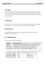
Page 35: ...dicator In the system has some LED and listed below Indicator Function Description HDD LED The LED will turn on when the hard disk drive is activated or accessed CDROM LED The LED will turn on when the CDROM drive is activated or accessed NumLock LED The LED will turn on when the function of NumLock is active CapsLock LED The LED will turn on when the function of CapsLock is active ScrollLock LED ...

Page 36: ...ternal Keyboards l Simultaneous Operation of Internal and External Auxiliary l Device Hot Pluggability l Hot Pluggability of External PS 2 Devices Keyboard or Mouse and Hot Port Swapping l Embedded Controller PC87591E 176 Pin LQFP package share BIOS l LPC System Interface l ACPI Embedded Controller Power Management Event Control l Internal 8 x 16 Keys Matrix Scanning l Single Pin Keys Support l PS...

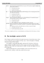
Page 37: ...control the battery charging and monitor power button Note Before enter to S4 the OS or BIOS will save all of data or registers in the parts 1 The system in the state S5 or S4 2 The CPU and all of devices power off When system in suspend mode S3 state external keyboard mouse and touch pad can t be the wake up event source H The backlight control of LCD The LCD panel is another key parts that will ...

Page 38: ......

Page 39: ...2 1 System Block Diagram 3 2 2 Major Component Definition 4 2 3 Connector Definition 35 TECHNICALSERVICEMANUAL PrestigioNobile159W 2 2 ...

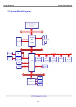
Page 40: ...ge 8 9 Page 11 12 13 IEEE 1394 IDE Hub Interface 66MHz OZ 711MC1 TI TSB43AB22 ATI M11P VIA VT1612A AC97 MINI PCI DDR SO DIMM EC MDC Page 3 4 MINI PCI Audio Codec 593 uFCBGA Page 5 6 7 RTL8100CL CD ROM PSB LED 1 5V AGP 66MHz BIOS ICH4M Intel 855PM 478 uFCPGA Secondary HDD Amplifier CPU Pentium M U2A TECHNICALSERVICEMANUAL PrestigioNobile159W 2 3 ...

Page 41: ...22 K24 L24 W25 W24 AE24 AE25 D25 J26 T24 AD20 A1 B2 C14 C3 AF7 C16 E1 A15 A16 B14 B15 A3 A4 A5 A6 A7 A8 A9 A10 A11 A12 A13 A14 A15 A16 A17 A18 A19 A20 A21 A22 A23 A24 A25 A26 A27 A28 A29 A30 A31 ADSTB 0 ADSTB 1 REQ0 REQ1 REQ2 REQ3 REQ4 D0 D1 D2 D3 D4 D5 D6 D7 D8 D9 D10 D11 D12 D13 D14 D15 D16 D17 D18 D19 D20 D21 D22 D23 D24 D25 D26 D27 D28 D29 D30 D31 D32 D33 D34 D35 D36 D37 D38 D39 D40 D41 D42 D4...

Page 42: ...VCC12 VCC13 VCC14 VCC15 VCC16 VCC17 VCC18 VCC19 VCC20 VCC21 VCC22 VCC23 VCC24 VCC25 VCC26 VCC27 VCC28 VCC29 VCC30 VCC31 VCC32 VCC33 VCC34 VCC35 VCC36 VCC37 VCC38 VCC39 VCC40 VCC41 VCC42 VCC43 VCC44 VCC45 VCC46 VCC47 VCC48 VCC49 VCC50 VCC51 VCC52 VCC53 VCC54 VCC55 VCC56 VCC57 VCC58 VCC59 VCC60 VCC61 VCC62 VCC63 VCC64 VCC65 VCC66 VCC67 VCC68 VCC69 VCC70 VCC71 VCCA0 VCCA1 VCCA2 VCCA3 VCCP0 VCCP1 VCCP...

Page 43: ...VSS24 VSS25 VSS26 VSS27 VSS28 VSS29 VSS30 VSS31 VSS32 VSS33 VSS34 VSS35 VSS36 VSS37 VSS38 VSS39 VSS40 VSS41 VSS42 VSS43 VSS44 VSS45 VSS46 VSS47 VSS48 VSS49 VSS50 VSS51 VSS52 VSS53 VSS54 VSS55 VSS56 VSS57 VSS58 VSS59 VSS60 VSS61 VSS62 VSS63 VSS64 VSS65 VSS66 VSS67 VSS68 VSS69 VSS70 VSS71 VSS72 VSS73 VSS74 VSS75 VSS76 VSS77 VSS78 VSS79 VSS80 VSS81 VSS82 VSS83 VSS84 VSS85 VSS86 VSS87 VSS88 VSS89 VSS9...

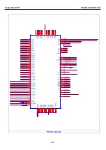
Page 44: ... 20 HA 21 HA 22 HA 23 HA 24 HA 25 HA 26 HA 27 HA 28 HA 29 HA 30 HA 31 HREQ 0 HREQ 1 HREQ 2 HREQ 3 HREQ 4 HADSTB 0 HADSTB 1 BCLK BCLK HRCOMP1 HSWNG1 HRCOMP0 HSWNG0 HDSTBN 0 HDSTBN 1 HDSTBN 2 HDSTBN 3 HDSTBP 0 HDSTBP 1 HDSTBP 2 HDSTBP 3 DBI 0 DBI 1 DBI 2 DBI 3 CPURST HVREF0 HVREF1 HVREF2 HVREF3 HVREF4 HI_0 HI_1 HI_2 HI_3 HI_4 HI_5 HI_6 HI_7 HI_8 HI_9 HI_10 HI_STB HI_STB HLRCOMP HI_REF HD 0 HD 1 HD 2...

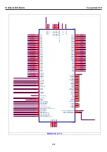
Page 45: ...QS5 SDQS6 SDQS7 SDQS8 SWE SCAS SRAS RSTIN RSVD1 TESTIN GAD0 GAD1 GAD2 GAD3 GAD4 GAD5 GAD6 GAD7 GAD8 GAD9 GAD10 GAD11 GAD12 GAD13 GAD14 GAD15 GAD16 GAD17 GAD18 GAD19 GAD20 GAD21 GAD22 GAD23 GAD24 GAD25 GAD26 GAD27 GAD28 GAD29 GAD30 GCBE 0 GCBE 1 GCBE 2 GCBE 3 GFRAME GDEVSEL GIRDY GTRDY GSTOP GPAR GREQ GGNT GRCOMP AGPREF 66IN AD_STB0 AD_STB 0 AD_STB1 AD_ATB 1 SBA0 SBA1 SBA2 SBA3 SBA4 SBA5 SBA6 SBA7 ...

Page 46: ...3 U15 U29 U4 U8 V22 V6 W1 W26 W4 W8 Y22 Y6 G1 G29 H10 H12 H14 H16 H18 H20 H22 H24 H5 H8 J6 K22 K24 K26 K7 L23 AF15 U17 GND GND GND GND GND GND GND GND GND GND GND GND GND GND GND GND GND GND GND GND GND GND GND GND GND GND VCCSM VCCSM VCCSM VCCSM VCCSM VCCSM VCCSM VCCSM VCCSM VCCSM VCCSM VCCSM VCCSM VCCSM VCCSM VTT VTT VTT VTT VCCSM VCCSM VTT VTT VCCSM VCCSM VTT VCCSM GND GND GND GND GND GND GND G...

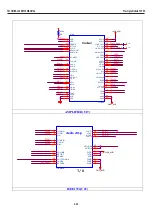
Page 47: ... 12 16 17 10 39 38 56 2 3 VDDREF VDDCPU VDDPCI VDDPCI VDD3V66 VDD3V66 VDD48 VDDCPU FS0 FS1 PWRSAVE PD PCI_STOP CPU_STOP Vtt_PWRGD MULTSEL SDATA GND SCLK 3V66_0 FS4 GND 3V66_1 VCH CLK FS3 IREF GND GND GND GND GND GND VDDA GND CPUCLKT2 CPUCLK2 E_PCICLK1 PCICLK1 CPUCLKC0 CPUCLKT1 CPUCLKC1 CPUCLKT0 3V66_5 3V66_4 3V66_3 3V66_2 ASEL PCICLK_F2 PCICLK_F1 PCICLK_F0 PCICLK6 E_PCICLK3 PCICLK3 PCICLK2 PCICLK4...

Page 48: ...CI_AD30 PCI_AD31 PCI_CBE0 PCI_CBE1 PCI_CBE2 PCI_CBE3 PCI_GNT0 PCI_GNT1 PCI_GNT2 PCI_GNT3 PCI_GNT4 PCI_REQ0 PCI_REQ1 PCI_REQ2 PCI_REQ3 PCI_REQ4 PCI_CLK PCI_DEVSEL PCI_FRAME PCI_REQA GPIO0 PCI_REQB REQ5 GPIO1 PCI_GNTA GPIO16 PCI_GNTB GNT5 GPIO17 PCI_IRDY PCI_PAR PCI_PERR PCI_LOCK PCI_PME PCI_RST PCI_SERR PCI_STOP PCI_TRDY CPU_A20GATE CPU_A20M CPU_FERR CPU_IGNNE CPU_INIT CPU_INTR CPU_NMI CPU_PWRGD CP...

Page 49: ...PDD11 IDE_PDD12 IDE_PDD13 IDE_PDD14 IDE_PDD15 IDE_SDD0 IDE_SDD1 IDE_SDD2 IDE_SDD3 IDE_SDD4 IDE_SDD5 IDE_SDD6 IDE_SDD7 IDE_SDD8 IDE_SDD9 IDE_SDD10 IDE_SDD11 IDE_SDD12 IDE_SDD13 IDE_SDD14 IDE_SDD15 IDE_PDDACK IDE_PDIOR IDE_PDIOW SPKR USB_PP0 USB_PP1 USB_PP2 USB_PP3 USB_PP4 USB_PP5 USB_PN0 USB_PN1 USB_PN2 USB_PN3 USB_PN4 USB_PN5 USB_OC0 USB_OC1 USB_OC2 USB_OC3 USB_OC4 USB_OC5 USB_RBIAS USB_RBIAS GPIO...

Page 50: ...VCC1_5 VCC1_5 VCC1_5 VCC1_5 VCC1_5 VCC1_5 VCC1_5 VCC3_3 VCC3_3 VCC3_3 VCC3_3 VCC3_3 VCC3_3 VCC3_3 VCC3_3 VCC3_3 VCC3_3 VCC3_3 VCC3_3 VCC3_3 VCC3_3 VCC3_3 VCC3_3 VCC_HUB VCC_HUB VCC_HUB VCC_HUB VCC_PLL VCCSUS1_5 VCCSUS1_5 VCCSUS1_5 VCCSUS1_5 VCCSUS1_5 VCCSUS1_5 VCCSUS1_5 VCCLAN1_5 VCCLAN1_5 VCCSUS1_5 VCCLAN3_3 VCCLAN3_3 VCCSUS3_3 VCCSUS3_3 VCCSUS3_3 VCCSUS3_3 VCCSUS3_3 VCCSUS3_3 VCCSUS3_3 VCCSUS3_3...

Page 51: ...A5 SBA6 SBA7 ST0 ST1 ST2 SB_STBS ADSTBS_0 ADSTBS_1 AGPREF AGPTEST R2SET C_R Y_G COMP_B H2SYNC V2SYNC DDC3CLK DDC3DATA SSIN SSOUT XTALIN XTALOUT TESTEN SUS_STAT GPIO0 GPIO1 GPIO2 GPIO3 GPIO4 GPIO5 GPIO6 GPIO7 GPIO8 GPIO9 GPIO10 GPIO11 GPIO12 GPIO13 GPIO14 GPIO15 GPIO16 ZV_LCDDATA0 ZV_LCDDATA1 ZV_LCDDATA2 ZV_LCDDATA3 ZV_LCDDATA4 ZV_LCDDATA5 ZV_LCDDATA6 ZV_LCDDATA7 ZV_LCDDATA8 ZV_LCDDATA9 ZV_LCDDATA1...

Page 52: ... DQA24 DQA25 DQA26 DQA27 DQA28 DQA29 DQA30 DQA31 DQA32 DQA33 DQA34 DQA35 DQA36 DQA37 DQA38 DQA39 DQA40 DQA41 DQA42 DQA43 DQA44 DQA45 DQA46 DQA47 DQA48 DQA49 DQA50 DQA51 DQA52 DQA53 DQA54 DQA55 DQA56 DQA57 DQA58 DQA59 DQA60 DQA61 DQA62 DQA63 MAA0 MAA1 MAA2 MAA3 MAA4 MAA5 MAA6 MAA7 MAA8 MAA9 MAA10 MAA11 MAA13 MAA12 MAA12 MAA13 DQMA 0 DQMA 1 DQMA 2 DQMA 3 DQMA 4 DQMA 5 DQMA 6 DQMA 7 QSA0 QSA1 QSA2 QS...

Page 53: ...19 DQB20 DQB21 DQB22 DQB23 DQB24 DQB25 DQB26 DQB27 DQB28 DQB29 DQB30 DQB31 DQB32 DQB33 DQB34 DQB35 DQB36 DQB37 DQB38 DQB39 DQB40 DQB41 DQB42 DQB43 DQB44 DQB45 DQB46 DQB47 DQB48 DQB49 DQB50 DQB51 DQB52 DQB53 DQB54 DQB55 DQB56 DQB57 DQB58 DQB59 DQB60 DQB61 DQB62 DQB63 MAB0 MAB1 MAB2 MAB3 MAB4 MAB5 MAB6 MAB7 MAB8 MAB9 MAB10 MAB11 MAB13 MAB12 MAB12 MAB13 DQMB 0 DQMB 1 DQMB 2 DQMB 3 DQMB 4 DQMB 5 DQMB ...

Page 54: ...DR1 VDDR1 VDDR1 VDDR1 VDDR1 VDDR1 VDDR1 VDDR1 VDDR1 VDDR1 VDDR1 VDDR1 VDDR1 VDDR1 VDDR1 VDDR1 VDDR1 VDDR1 VDDR1 VDDR1 VDDR1 LPVDD LVDDR_18 LVDDR_18 LVDDR_25 LVDDR18_25 LVDDR_25 LVDDR18_25 LPVSS LVSSR LVSSR LVSSR LVSSR TPVDD TPVSS TXVDDR TXVDDR TXVSSR TXVSSR TXVSSR A2VDD A2VDD A2VDDQ AVDD A2VSSN VSS2DI A2VSSQ VDDR1 VDDR1 VDDR1 VDDR1 VDDR1 VDDR1 VDDR1 VDDR1 VDDR1 VDDR1 CLKBFB VDDR1 VDDR1 VDDRH0 VDDR...

Page 55: ...18 AD16 AD12 AE27 AG5 AG9 AG11 AG15 AG18 AG22 AG27 AJ1 AJ30 AK29 AK2 D10 D25 E4 AB4 VSS VSS VSS VSS VSS VSS VSS VSS VSS VSS VSS VSS VSS VSS VSS VSS VSS VSS VSS VSS VSS VSS VSS VSS VSS VSS VSS VSS VSS VSS VSS VSS VSS VSS VSS VSS VSS VSS VSS VSS VSS VSS VSS VSS VSS VSS VSS VSS VSS VSS VSS VSS VSS VSS VSS VSS VSS VSS VSS VSS VSS VSS VSS VSS VSS VSS VSS VSS VSS VSS VSS VSS VSS VSS VSS VSS VSS VSS VSS ...

Page 56: ...W13 W14 N13 N19 M19 M18 M12 N12 M13 M14 P12 P13 P14 M17 VDDC VDDC VDDC VDDC VDDC VDDC VDDC VDDC VDDC VDDC VSS VSS VSS VSS VSS VSS VSS VSS VSS VDDC VDDC VDDC VDDC VDDC VDDC VDDC VDDC VSS VSS VSS VSS VSS VSS VSS VSS VDDC VDDC VSS VSS VSS VSS VSS VSS VSS VDDC1 VDDC1 VDDC1 VDDC1 VDDC1 VDDC VDDC VDDC VDDC VDDC VDDC VDDC VDDC VDDC VDDC VDDC VDDC VDDC VDDC VDDC V1 2S_M11 VDDC1 V1 2S_M11 DDR CHANNELA U13 ...

Page 57: ...13 DQ14 DQ15 VDD VDD VDD VDDQ A12 VDDQ VDDQ VDDQ VSS VSS VSS A10 AP CLK VSSQ VSSQ VSSQ VSSQ VSSQ LDQS UDQS LDM UDM NC1 NC1 NC1 NC1 NC1 NC1 NC1 MEM_MAA7 TZ1803 MEM_MAA0 MEM_QSA2 MEM_CASA MEM_MAA6 MEM_MDA5 TZ1818 MEM_MDA11 TZ1801 TZ1822 V2 5S MEM_MAA14 MEM_CSA0 MEM_RASA MEM_MDA9 MEM_MDA14 U38 8Mx16_K4D261638F TC40 49 29 30 31 32 35 36 37 38 39 26 27 40 23 22 21 24 45 44 41 9 2 4 5 7 8 10 11 13 54 56...

Page 58: ...37 38 39 26 27 40 23 22 21 24 45 44 41 9 2 4 5 7 8 10 11 13 54 56 57 59 60 62 63 65 1 18 33 3 42 15 55 61 34 48 66 28 46 6 12 52 58 64 16 51 20 47 14 17 19 25 43 50 53 VREF A0 A1 A2 A3 A4 A5 A6 A7 A8 BA0 BA1 A9 RAS CAS WE CS CLK CKE A11 VDDQ DQ0 DQ1 DQ2 DQ3 DQ4 DQ5 DQ6 DQ7 DQ8 DQ9 DQ10 DQ11 DQ12 DQ13 DQ14 DQ15 VDD VDD VDD VDDQ A12 VDDQ VDDQ VDDQ VSS VSS VSS A10 AP CLK VSSQ VSSQ VSSQ VSSQ VSSQ LDQS...

Page 59: ...MDB2 MEM_MAB3 MEM_MAB11 MEM_CASB MEM_MAB5 DDRVREFB0 MEM_MDB24 MEM_MDB26 MEM_CLKB0 TZ1920 MEM_DQMB 3 MEM_MAB11 MEM_CSB0 MEM_MAB2 MEM_WEB MEM_MAB10 MEM_MDB30 TZ1901 MEM_MDB18 TZ1919 TZ1907 MEM_CKEB MEM_MAB7 MEM_MAB12 MEM_MAB0 MEM_MDB23 MEM_MDB25 TZ1922 MEM_MAB13 MEM_MAB6 U34 8Mx16_K4D261638F TC40 49 29 30 31 32 35 36 37 38 39 26 27 40 23 22 21 24 45 44 41 9 2 4 5 7 8 10 11 13 54 56 57 59 60 62 63 65...

Page 60: ...33 TZ1930 MEM_MDB49 TZ1931 MEM_MAB13 MEM_MDB59 MEM_MAB2 MEM_MDB45 MEM_CLKB1 MEM_MAB0 MEM_MAB9 U6 8Mx16_K4D261638F TC40 49 29 30 31 32 35 36 37 38 39 26 27 40 23 22 21 24 45 44 41 9 2 4 5 7 8 10 11 13 54 56 57 59 60 62 63 65 1 18 33 3 42 15 55 61 34 48 66 28 46 6 12 52 58 64 16 51 20 47 14 17 19 25 43 50 53 VREF A0 A1 A2 A3 A4 A5 A6 A7 A8 BA0 BA1 A9 RAS CAS WE CS CLK CKE A11 VDDQ DQ0 DQ1 DQ2 DQ3 DQ...

Page 61: ...T SDATA IN PC BEEP PHONE AUX L AUX R VIDEO L VIDEO R CD L CD R MIC1 MIC2 LINE L LINE R VSS VSS AVSS AVSS XTL IN XTL OUT LINE OUTL LINE OUTR MONO OUT VREF VREFOUT AFILT1 AFILT2 VRAD VRDA DC_VOL VAUX JD SDIN1 TEST1 ID0 ID1 EAPD SPDIFO HP OUT L NC HP OUT R CD GND VDD VDD AVDD AVDD AMPLIFIER U19 Audio Amp U19 TPA6011A 1 2 3 7 11 12 13 14 18 24 8 9 10 4 5 6 19 20 21 15 16 17 22 23 PGND ROUT PVDD VDD PV...

Page 62: ..._AD25 PCI_AD26 PCI_AD27 PCI_AD28 PCI_AD29 PCI_AD30 PCI_AD31 PCI_CBE0 PCI_CBE1 PCI_CBE2 PCI_CBE3 PCI_CLK PCI_PAR PCI_FRAME PCI_TRDY PCI_IRDY PCI_STOP PCI_IDSEL PCI_REQ PCI_GNT PCI_PERR PCI_SERR PCI_DEVSEL PCI_RST PCI_INTA PCI_PME SCL A G N D A G N D D G N D D G N D D G N D D G N D D G N D D G N D D G N D D G N D D G N D D G N D R E G 1 8 R E G 1 8 A G N D A G N D D V D D D V D D D V D D D V D D D V...

Page 63: ...2_A18 CVS1 CVS2 CCD1 CCD2 CAUDIO CSTSCHG CC BE3 CC BE2 CC BE1 CC BE0 AD31 AD30 C BE3 C BE2 C BE1 C BE0 IDSEL PCI_CLK DEVSEL FRAME IRDY TRDY STOP PAR PERR SERR REQ GNT RST RI_OUT PME SPKR_OUT MF6 CLKRUN MF3 IRQSER MF0 INTA GND GND GND GND GND GND AD16 AD17 AD18 AD19 AD20 AD21 AD22 AD23 AD24 AD25 AD26 AD27 AD28 AD29 AD0 AD1 AD2 AD3 AD4 AD5 AD6 AD7 AD8 AD9 AD10 AD11 AD12 AD13 AD14 AD15 CORE_VCC SUSPE...

Page 64: ...NC HSDAC AVDD25 NC NC N C VSS VSS NC MDI2 NC MDI2 N C AVD D L AVD D L GN D VSS VSS NC MDI3 NC MDI3 AVD D 33 AVD D L AVD D L GN D VSSPST VSSPST N C GN D GN D ISOLATEB N C VD D 18 VD D 12 INTAB VD D 33 RSTB CLK GNTB REQB PMEB VD D 25 VD D 18 VD D 12 AD31 AD30 GN D AD29 AD28 GN D VSSPST VSSPST AD27 AD26 VD D 33 AD25 AD24 CBE3B N C VD D 18 VD D 12 IDSEL AD23 N C GN D GN D AD22 AD21 GN D VSSPST VSSPST ...

Page 65: ...VSTBY VSTBY VSS VSS FA8 ID0 FA9 ID1 FA10 ID2 FA11 ID3 FA12 FA13 FA14 FA15 FA16 GPG1 FA17 GPG2 FA18 GPG3 FA19 FCS DAC4 DAC5 LAD0 PS2CLK0 GPCF0 PS2DAT0 GPCF1 PS2CLK1 GPCF2 PS2DAT1 GPCF3 PS2CLK2 GPCF4 PS2DAT2 GPCF5 PS2CLK3 GPCF6 PS2DAT3 GPCF7 DAC0 DAC1 DAC2 DAC3 ADC0 ADC1 ADC2 ADC3 ADC4 GPE0 ADC5 GPE1 ADC6 GPE2 ADC7 GPE3 PWRSW GPE4 WUI5 GPE5 LPCPD WUI6 GPE6 CLKRUN WUI7 GPE7 RI1 WUI0 GPD0 RI2 WUI1 GPD...

Page 66: ...BST5 DL5 PGND V L V SHDN DL3 BST3 PHASE3 DH3 RUN ON 3 Z3606 Z3616 PR56 10K 1 2 Z3623 Z3615 Z3605 Z3608 Z3610 Z3607 Z3628 Z3609 VCORE PU12 PU12 LTC3734 1 2 3 5 6 7 8 4 9 10 11 12 13 14 15 16 17 18 19 20 21 22 23 24 25 26 27 28 29 30 31 32 VOA VOA OAOUT SGND SENSE SENSE RDPRSLP STP_CPUB RDPSLP RUN SS ITH RBOOT VID0 VID1 VID2 N C VID3 VID4 VID5 PGND BG PVCC SW TG BOOST PGOOD MCH_PG VFB SVCC DPRSLPVR ...

Page 67: ...SE2 PGND2 LGATE2 VCC 1 2V 1 5 POWER PU8 Z3904 Z3913 Z3907 PU8 ISL6225CA 1 2 3 4 5 6 7 8 9 10 11 12 13 14 15 16 17 18 19 20 22 23 21 24 25 26 27 28 GND LGATE1 PGND1 PHASE1 UGATE1 BOOT1 ISEN1 EN1 VOUT1 VSEN1 OCSET1 SOFT1 DDR VIN PG1 PG2 REF SOFT2 OCSET2 VSEN2 VOUT2 ISEN2 BOOT2 EN2 UGATE2 PHASE2 PGND2 LGATE2 VCC Z3906 Z3905 PC106 0 1U 25V 2 1 Z3909 Z3908 Z3903 2 3 Connectors Definition TECHNICALSERVI...

Page 68: ...0 158 89 91 VREF VREF NC NC A9 A7 A5 A4 A2 A1 A0 BA1 BA0 WE CAS NC A13 SDA SCL NC VddSPD A12 A11 A8 A6 A3 A10 AP RAS NC BA2 NC VddID SA0 SA1 SA2 NC RESET VDD VDD VDD VDD VDD VDD VDD VDD VDD VDD VDD VDD VDD VDD VDD VDD VDD VDD VDD VDD VDD VDD VDD VDD VDD VDD VDD VDD VDD VDD VDD VDD VDD VSS VSS VSS VSS VSS VSS VSS VSS VSS VSS VSS VSS VSS VSS VSS VSS VSS VSS VSS VSS VSS VSS VSS VSS VSS VSS VSS VSS VS...

Page 69: ...1 VREF VREF NC NC A9 A7 A5 A4 A2 A1 A0 BA1 BA0 WE CAS NC A13 SDA SCL NC VddSPD A12 A11 A8 A6 A3 A10 AP RAS NC BA2 NC VddID SA0 SA1 SA2 NC RESET VDD VDD VDD VDD VDD VDD VDD VDD VDD VDD VDD VDD VDD VDD VDD VDD VDD VDD VDD VDD VDD VDD VDD VDD VDD VDD VDD VDD VDD VDD VDD VDD VDD VSS VSS VSS VSS VSS VSS VSS VSS VSS VSS VSS VSS VSS VSS VSS VSS VSS VSS VSS VSS VSS VSS VSS VSS VSS VSS VSS VSS VSS VSS VSS ...

Page 70: ...CONN CN6 CN6 S VIDEO_35146S 04T1 F S VIDEO_CONN 2 3 4 1 5 6 TV_GND LCD CONN CN3 TXD5 TXD1 TXC0 LDDCCLK TXD1 TXD5 LDDCDATA PNLID1 V3 3S_LCD CN3 ACES 87216 3012 LCD_CON 1 2 3 4 5 6 7 8 9 10 11 12 13 14 15 16 17 18 19 20 21 22 23 24 25 26 27 28 29 30 TXC0 TXC1 TXC1 V3 3S_LCD TV IN CONN CN1 TECHNICALSERVICEMANUAL PrestigioNobile159W 2 33 ...

Page 71: ...N TV BOARD CONN CN4 CN4 TV BOARD CON 1 2 3 4 5 6 7 8 1 2 3 4 5 6 7 8 CRT CONN CN2 TZ2101 CN2 D SUB_15P_DZ11A91 WL_31 CRT_CONN 15 14 13 12 11 1 2 3 4 5 6 7 8 9 10 16 17 Z2110 C329 22P 2 1 C330 22P 2 1 Z2111 Z2107 TZ2102 DVD CONN CN9 TECHNICALSERVICEMANUAL PrestigioNobile159W 2 34 ...

Page 72: ...IDE_SDD9 TZ2203 IDE_SDDREQ IDE_SDIOR IDE_SDD10 IDE_SDD15 TZ2202 IDE_SDDACK IDECD_R HDD CONN CN31 TZ2206 IDE_PDD11 IDE_PDD10 IDE_PDD9 IDE_PDD15 IDE_PDD13 IDE_PDA2 CN31 HDD CONN 1 2 3 4 5 6 7 8 9 10 11 12 13 14 15 16 17 18 19 20 21 22 23 24 25 26 27 28 29 30 31 32 33 34 35 36 37 38 39 40 41 42 43 44 45 46 IDE_PATADET V5S_HDD IDE_PD_CSEL IDE_PDD14 IDE_PDD12 IDE_PDCS3 V5S_HDD TZ2204 IDE_PDD8 TZ2205 US...

Page 73: ...0K 1 2 CN33 88018 3000 0 8MM MDC_CONN 1 3 5 7 9 11 13 15 17 19 21 23 25 27 29 30 28 26 24 22 20 18 16 14 12 10 8 6 4 2 MONO_OUT GND AUXR AUXL CD_GND CD_R CD_L GND 3 3Vaux dual GND 3 3Vmain SDATA_OUT RESET GND MSTRCLK BITCLK GND SDATA_INA SDATA_INB SYNC GND 5V PRIMARY_DN RES RES 5Vmain GND RES MONO_PHONE AUDIO_PD R290 33R 1 2 R288 0R 1 2 MDCLK AC_SYNC TZ2312 TZ2309 TZ2311 Z2303 05 29 Modify AC_SDAT...

Page 74: ... S820 027 MIC_JACK 1 2 6 3 5 4 7 8 TZ2503 GND_AUD MIC JACK CONN CN36 GND_AUD 4 28 follow 255ii CN36 2SJ S820 027 MIC_JACK 1 2 6 3 5 4 7 8 1394 CONN CN26 TPB0 1394 CN26 MOLEX 1394_54030 0491 1394_CONN 1 2 3 4 5 6 TPB TPB TPA TPA SHLD SHLD TPB0 1394 TPA0 1394 TPA0 1394 LINE IN CN29 TECHNICALSERVICEMANUAL PrestigioNobile159W 2 37 ...

Page 75: ...Z2528 GND_AUD Z2527 CN29 2SJ S820 027 LINE_IN 1 2 6 3 5 4 7 8 TZ2504 C126 1000P 2 1 TZ2505 4 28 follow 255ii C133 1000P 2 1 TZ2506 05 28 TECHNICALSERVICEMANUAL PrestigioNobile159W 2 38 ...

Page 76: ......

Page 77: ...3 1 TOP Cabinet Assembly 3 3 2 BUTTOM Cabinet Assembly 4 3 3 ODD Cabinet Assembly 5 3 4 LCD Assembly 6 TECHNICALSERVICEMANUAL PrestigioNobile159W 3 2 ...

Page 78: ...M PART NO DESCRIPTION QTY A 22 325040 00 SPEAKER SUB WOOFER 25SB04 259IA1 1 B XXXXXX MB 259IA1 1 C 83 UG8010 00 TOP CAB ASSY 8100 8151 259IA1 1 D 35 UG8050 00 HDD TRANSFER BD 259IA1 1 TECHNICALSERVICEMANUAL PrestigioNobile159W 3 3 ...

Page 79: ...40 00 THERMAL MODULE YDT BISONIC 255 259IAX 1 C 83 UG6020 00 BTM CAB ASSY W O TV 8155 259IA1 1 D 52 UG5012 00 RUBBER FOOT ADD 2MM FOR 255II1 1 E 50 UG5010 00 COVER HDD 8155 255II1 1 F 86 UG5020 01 HDD ASSY 40GB 255II1 1 G 50 UG5061 00 DOOR USB DONGLE 8155 255II1 1 TECHNICALSERVICEMANUAL PrestigioNobile159W 3 4 ...

Page 80: ... 8155 255II1 1 2 50 UG5076 00 KNOB DVD DUAL QSI 8155 1 3 70 240006 10 DVD DUAL SDW 042 4X QUANTA FW DX71 1 4 40 UG6023 00 MYLAR HDD PULL BAR 258SA0 1 5 41 720120 04 SCREW M2 0 4 I 1 NI 2 6 41 910217 03 SCREW TP1 7 3 I 0 BLACK H 0 6 1 TECHNICALSERVICEMANUAL PrestigioNobile159W 3 5 ...

Page 81: ...3 6 LCD Module Assembly TECHNICALSERVICEMANUAL PrestigioNobile159W 3 6 ...

Page 82: ...INVERTER 259IA1 1 8 40 UG6025 00 HINGE BKT LCD R 15 4 HONTECH 159IA1 1 9 72 115262 00 LCD 15 4 TFT WXGA QD15TL01 QDI 1 10 50 UG8211 00 MYLAR LCD FRONT 8151 259IA1 2 11 50 UG6030 00 FRONT CAB 8151 259IA1 1 12 52 UG8030 00 RUBBER LCD UP 8155 259IA1 4 13 40 UG6025 10 HINGE BKT LCD L 15 4 HONTECH 259IA1 1 14 29 UG8054 00 CABLE LCD 15 4 WXGA CMI 259IA1 1 15 41 720102 03 SCREW M2 3 I 0 D2 8 3 1 T0 3 0 4...

Page 83: ......

Page 84: ...4 1 System Disassembly Procedures 3 4 2 LCD Display Panel Disassembly Procedure 11 TECHNICALSERVICEMANUAL PrestigioNobile159W 4 2 ...

Page 85: ...cedures 1 Please refer to the disassembly procedures of the Nobile 159W 2 Unlock the battery knob and pull out the battery pack 3 Unfasten 6 screws and remove the CPU and DDR cover TECHNICALSERVICEMANUAL PrestigioNobile159W 4 3 ...

Page 86: ...4 Unfasten 1 screw and remove the ODD 5 Unfasten 5 screws 6 a Unlock CPU lock and remove CPU b Gently remove the DDR TECHNICALSERVICEMANUAL PrestigioNobile159W 4 4 ...

Page 87: ...7 Unfasten 1 screw of the HDD cover 8 Disconnect the HDD casing to the HDD Connector to remove it 9 Unfasten 20 screws TECHNICALSERVICEMANUAL PrestigioNobile159W 4 5 ...

Page 88: ...10 Unfasten 3 screws 11 Unlock 3 Latches of the Keyboard 12 Disconnect KB cable from the connector TECHNICALSERVICEMANUAL PrestigioNobile159W 4 6 ...

Page 89: ...13 Remove 2 hinge cover and speaker cover 14 Disable LCD cable 15 Unfasten 4 screws from LCD hinge TECHNICALSERVICEMANUAL PrestigioNobile159W 4 7 ...

Page 90: ...16 Unlock LCD Knob and gently remove LCD panel 17 Gently remove Bottom cover 18 Disconnect USB cable TECHNICALSERVICEMANUAL PrestigioNobile159W 4 8 ...

Page 91: ...ker cable and unfasten 2 hexnuts 23 a Remove 1 hexnuts and 2 screws b Unplug touch pad cable and HDD cable c Remove 4 cables 24 Remove 2 screws before remove modem board TECHNICALSERVICEMANUAL PrestigioNobile159W 4 9 ...

Page 92: ...25 System Disassembly TECHNICALSERVICEMANUAL PrestigioNobile159W 4 10 ...

Page 93: ...4 2 LCD Display disassembly procedure 1 Remove the 6 rubber stoppers 2 Unfasten 6 screws 3 Gently remove the LCD Front cabinet TECHNICALSERVICEMANUAL PrestigioNobile159W 4 11 ...

Page 94: ...nfsaten 12 screws 5 Disconnect LCD cable from the inverter board and remove the LCD from LCD back cabinet 6 Unfasten 8 screws and remove left and right hinge TECHNICALSERVICEMANUAL PrestigioNobile159W 4 12 ...

Page 95: ...7 Disconnect LCD connector and remove LCD cable 8 LCD display panel disassembly finished TECHNICALSERVICEMANUAL PrestigioNobile159W 4 13 ...

Page 96: ......

Page 97: ...5 1 CPU RAM HDD Installation 3 5 2 Upgrade System Keyboard BIOS 8 TECHNICALSERVICEMANUAL PrestigioNobile159W 5 2 ...

Page 98: ...A CPU Installation Guide Important Notice The CPU thermal pad of the CPU fan heat sink black color is one time use only Meaning that if you remove the CPU heat sink from the CPU you must REPLACE the CPU thermal pad with a new thermal pad black color Clean any residue on the CPU and the CPU heat sink assembly before putting the new CPU thermal pad Otherwise there might be an overheat problem on the...

Page 99: ...PU Fan cover and disconnect Fan cable from the connector 3 Align the pin 1 of CPU with pin 1 of CPU socket and gently put the CPU into the CPU socket 4 Fasten the CPU Lock clockwise TECHNICALSERVICEMANUAL PrestigioNobile159W 5 4 ...

Page 100: ...5 Fasten 5 screws from CPU Fan cover and connect Fan cable from the connector 6 Put CPU and DDR cover then fasten 6 screws TECHNICALSERVICEMANUAL PrestigioNobile159W 5 5 ...

Page 101: ...B HDD Installation Guide 1 Fasten 4 screws of HDD module 2 Unfasten 1 screw of the HDD cover 3 Push the HDD casing into the HDD connector TECHNICALSERVICEMANUAL PrestigioNobile159W 5 6 ...

Page 102: ...4 Fasten 1 screw of the HDD cover TECHNICALSERVICEMANUAL PrestigioNobile159W 5 7 ...

Page 103: ... DDR Module Installation Guide 1 Unfasten 6 srews of the CPU and DDR cover 2 Put the DDR Module to the DDR socket 3 Fasten 6 srews of the CPU and DDR cover TECHNICALSERVICEMANUAL PrestigioNobile159W 5 8 ...

Page 104: ...er is connected to your notebook before you run this utility 2 Please make a clean Boot Disk which has no config sys and autoexec bat files 3 Boot from Floppy disk enter DOS prompt 4 Type DIR 5 Please make sure the diskette has the following files F82745EXE and xxxx xxx Bios Filename 6 Start to update the system BIOS AC power must plug into unit Type A F82745 xxxx xxx 7 Press Enter After updating ...

Page 105: ......

Page 106: ...6 7 Touch pad test error 6 8 Memory Card bus Failure 6 9 Hard disk drive test error 6 10 CMOS test error 6 11 IEEE 1394 Failure 6 12 Card read port test error 6 13 Audio failure 6 14 No power symptom 6 15 CD ROM drive test error 6 16 Stopping in LCD screen while booting 6 17 PCMCIA Card Bus failure 6 18 Modem Failure 6 19 LAN Failure 6 20 TV OUT Failure TECHNICALSERVICEMANUAL PrestigioNobile159W 6...

Page 107: ...em failure Symptom There is no display on both LCD and Monitor after power on although the LCD and Monitor are known good NoDisplay MonitororLCDmoduleok Replace monitor or LCD Display Ok Replace motherboard NO Yes Yes No Yes Yes NO NO Yes TECHNICALSERVICEMANUAL PrestigioNobile159W 6 3 ...

Page 108: ...place Motherboard Screen distortion Replace Motherboard Check Memory Size Replace Motherboard Correct it 6 2 VGA controller failure Symptom There is no display or distortion on both LCD and Monitor although Power On Self Test is passed Yes No No No Yes Yes No Yes TECHNICALSERVICEMANUAL PrestigioNobile159W 6 4 ...

Page 109: ...CD shows nothing or abnormal picture but it is ok for external monitor LCD No Display Try another known good LCD module Display OK No Yes Replace each parts of LCD module cables and test Replace motherboard TECHNICALSERVICEMANUAL PrestigioNobile159W 6 5 ...

Page 110: ...ptom The CRT monitor shows nothing or abnormal color but it is ok for LCD Monitor No Display Try another known good monitor Replace faulty monitor Correct it Display Ok Setup Ok Replace motherboard No Yes No Yes TECHNICALSERVICEMANUAL PrestigioNobile159W 6 6 ...

Page 111: ...Memory test error Try another known good DRAM module Test OK Replace the faulty DRAM module Replace motherboard 6 5 Memory test error No Yes TECHNICALSERVICEMANUAL PrestigioNobile159W 6 7 ...

Page 112: ...f keyboard failure is shown or any key doesn t work Keyboard test error Is K B cable connected to M B properly Connect or Replace K B cable Try another good keyboard Test Ok Replace the faulty keyboard Replace motherboard No No Yes Yes TECHNICALSERVICEMANUAL PrestigioNobile159W 6 8 ...

Page 113: ... cable connected properly 6 7 Touch Pad test error Symptom An error message is shown when the Touch Pad point is enabled Touch pad error Try another known good touch pad module and cable Test Ok Replace the faulty parts Replace motherboard Yes No TECHNICALSERVICEMANUAL PrestigioNobile159W 6 9 ...

Page 114: ...tect Device with removable storage Correct it Test Ok Replace Motherboard Yes No 1 Check Memory Card Bus Device in Windows XP if it is properly installed including driver 2 Try Reinsert Memory Stick Memory Card Bus failure TECHNICALSERVICEMANUAL PrestigioNobile159W 6 10 ...

Page 115: ...e drive motor spins non stop while reading data from or writing data to Hard disk Hard disk test error Replace the faulty parts Re boot ok Replace motherboard Yes No Try another known good HDD Check BIOS Setup OK Correct it Yes No TECHNICALSERVICEMANUAL PrestigioNobile159W 6 11 ...

Page 116: ...time data No CMOS test error 1 Plug in AC adapter power on the system and set correct data in BIOS setup 2 Replace CMOS Battery 3 Turn off power for 1 hour then turn on again Re boot OK END Replace motherboard Yes TECHNICALSERVICEMANUAL PrestigioNobile159W 6 12 ...

Page 117: ... t detect the device IEEE 1394 Failure Re test Ok Correct it Replace Motherboard Yes No 1 Check IEEE 1394 device in Windows XP if it is properly installed including driver 2 Try another backup HDD using IEEE 1394 device TECHNICALSERVICEMANUAL PrestigioNobile159W 6 13 ...

Page 118: ...Can t get this card read Card read fail 1 check whether driver are installed properly 2 try another working Card read Correct it Re test OK Setup OK Correct it Replace motherboard Yes Yes No No TECHNICALSERVICEMANUAL PrestigioNobile159W 6 14 ...

Page 119: ...rive is installed Audio test error 1 check whether cables speakers audio drivers are installed properly 2 try another working speaker cable Correct it Re test ok Setup ok Replace motherboard Yes No No Yes Correct it TECHNICALSERVICEMANUAL PrestigioNobile159W 6 15 ...

Page 120: ... Symptom When the power button is pressed nothing happens power indicator is not light up Correct it Check Adapter is good Replace Bios ok No Power Yes No Replace motherboard TECHNICALSERVICEMANUAL PrestigioNobile159W 6 16 ...

Page 121: ...is shown when reading data from CD ROM drive CD ROM driver test error Replace the faulty parts Re boot ok Replace motherboard Yes No Try another known good CD ROM Check BIOS Setup OK Correct it Yes No TECHNICALSERVICEMANUAL PrestigioNobile159W 6 17 ...

Page 122: ...ting Replace Bios ok Yes No Yes Replace Motherboard Stop in LCD Screen while booting 1 Try another known good CD ROM 2 Try another known good HDD 3 Try another known good CPU 4 Thermal modle deformation TECHNICALSERVICEMANUAL PrestigioNobile159W 6 18 ...

Page 123: ...CMCIA card to PCMCIA slot but system can t detect PCMCIA card failure Insert PCMCIA card completely again make sure good connection Check drive controller install OK Correct it Replace Motherboard Yes No TECHNICALSERVICEMANUAL PrestigioNobile159W 6 19 ...

Page 124: ...em failure Modem Failure Check Driver install Telephone Line is OK Replace another known good Modem board Replace Motherboard Correct it Correct it No Yes Yes No TECHNICALSERVICEMANUAL PrestigioNobile159W 6 20 ...

Page 125: ... enter internet Correct it Re test Ok Replace Motherboard Yes No 1 Check Network Adapter Device in Windows XP if it is properly Installed including driver 2 Setup Network Connections in Windows XP 3 Reinsert LAN cable LAN failure TECHNICALSERVICEMANUAL PrestigioNobile159W 6 21 ...

Page 126: ...d Yes No 2 Check Display adapter Device in Windows XP if it is properly installed including driver 3 Check S Vedio cable if is properly insert TV 4 Setup display properties to select TV in Windows XP TV Out failure TECHNICALSERVICEMANUAL PrestigioNobile159W 6 22 ...

Page 127: ...www prestigio com ...

Reviews: