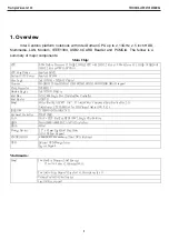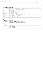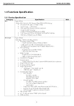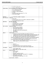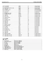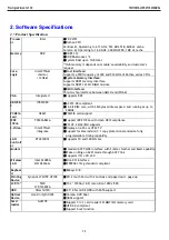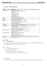
caused by PCB’s layout. According to the H/W architecture , the BIOS will recognize it as a PCI device and initialize it in PCI
bus initialization. The PCI legacy audio mode is not to be supported.
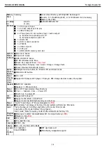
2.4.4 Modem
The system can use all of the modem that is AC97’ compliance and the MDC form factor. During POST, the BIOS will
detect the existence the MDC and set proper registers in south bridge
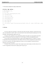
2.4.5 PCMCIA
The
OZ
601T
supports a variety of features . PCcard , CardBus
2.4.6 Card
Reader
Card Reader via USB bus, support SD Card , MMC, Memory Stick, Memory Stick Pro
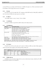
2.4.7 LED
Indicator
Indicator
Function Description
Power/Suspend LED
The LED will turn blink green when system is suspend
Charge LED
The LED will always off when without Battery
The LED will turn on green when Battery Full Charged
The LED will turn on orange when Battery Charging
The LED will turn on red when Battery Low warning
Wireless LED
1. Setup menu can define RF enable or disable
2. Load default = RF enable , The LED will turn on blue
3. Without WALN card = always disable
4. Into suspend = RF disable
5. Before Power off & Suspend need keep RF status for setting next power on & resume .
Silent LED
The LED will turn on when system entry silent mode
Num Lock LED
The LED will turn on when Num Lock function is activated
Cap Lock LED
The LED will turn on when Cap Lock function is activated
HDD/CDROM LED
The LED will turn on when the hard disk or CDROM is activated or accessed
Power on the system will turn on Cap, ,Num lock LED about 1~2 seconds then turn off them.
.
2.4.8 PCI
Device
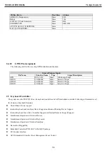
All the PCI devices will occupy the system resources, such as I/O, Memory and IRQ, especially the IRQ assignment is
relative to H/W and system arrangement. The following will list all PCI devices:
PCI Device
IDSEL
Bus#
Device#
Func#
INT Pin
Device Name
PAD20 1
3
0
B
OZ601
PCMCIA
PAD26 1
10
0
A
TI
TSB43AB22A
IEEE-1394
PAD28 1
12
0
A
LAN
RTL8100CL
PAD19
1
7
0
A, B
MINI PCI DEVICES
2.4.9 SMBus
Devices
The SMBus is a two-wire interface through which the system can communicate with power-related chips. The BIOS
should initialize the SMBus devices during POST.
TECHNICAL SERVICE MANUAL
Prestigio Visconte 130
17
Summary of Contents for VISCONTE 130
Page 1: ...PRESTIGIOVISCONTE 130 TECHNICAL SERVICE MANUAL ...
Page 27: ...TECHNICAL SERVICE MANUAL PrestigioVisconte 130 27 ...
Page 29: ...2 1 System Block Diagram TECHNICAL SERVICE MANUAL PrestigioVisconte 130 29 ...
Page 40: ...Intel 915GM Alviso U34H TECHNICAL SERVICE MANUAL PrestigioVisconte 130 40 ...
Page 41: ...TECHNICAL SERVICE MANUAL PrestigioVisconte 130 41 ...
Page 43: ...SB ICH 6M U19A TECHNICAL SERVICE MANUAL PrestigioVisconte 130 43 ...
Page 57: ...ODD CONN CON11 CARDBUS 1 CON100 TECHNICAL SERVICE MANUAL PrestigioVisconte 130 57 ...
Page 59: ...USB CONN MCN4 MCN5 USB CONN MCN2 TECHNICAL SERVICE MANUAL PrestigioVisconte 130 59 ...
Page 63: ...TECHNICAL SERVICE MANUAL PrestigioVisconte 130 63 ...
Page 64: ...Page 38 39 TECHNICAL SERVICE MANUAL PrestigioVisconte 130 64 ...
Page 65: ...TECHNICAL SERVICE MANUAL PrestigioVisconte 130 65 ...
Page 66: ...TECHNICAL SERVICE MANUAL PrestigioVisconte 130 66 ...
Page 69: ...TECHNICAL SERVICE MANUAL PrestigioVisconte 130 69 ...
Page 70: ...TECHNICAL SERVICE MANUAL PrestigioVisconte 130 70 ...
Page 71: ...3 2 ODD Assembly TECHNICAL SERVICE MANUAL PrestigioVisconte 130 71 ...
Page 72: ...3 3 LCD Module Assembly TECHNICAL SERVICE MANUAL PrestigioVisconte 130 72 ...
Page 73: ...TECHNICAL SERVICE MANUAL PrestigioVisconte 130 73 ...
Page 74: ...TECHNICAL SERVICE MANUAL PrestigioVisconte 130 74 ...
Page 88: ...8 LCD display panel disassembly finished TECHNICAL SERVICE MANUAL PrestigioVisconte 130 88 ...
Page 89: ...TECHNICAL SERVICE MANUAL PrestigioVisconte 130 89 ...
Page 95: ...TECHNICAL SERVICE MANUAL PrestigioVisconte 130 95 ...
Page 120: ...www prestigio com ...

