background image

PRESTO OWNER’S MANUAL 

Page 9 

POWER STAK PPS3000-125FS 

S E C T I O N  5

BATTERY MAINTENANCE

A.  PREPARING TO CHARGE A BATTERY

1. Always turn off E-stop and key switch before working

with the batteries.

2. Be sure the area around the stacker and the battery is

well ventilated while battery is being charged. 

3. The battery terminals, connections and wiring connec-

tions should be clean and free of corrosion. When clean-

ing any of these components wear a face shield or other

suitable protective eyewear.

B.  BATTERY CHARGING

Charging must be performed with the charger that is provided 

with or prewired into the machine.  During charging, the 

temperature in the battery must not exceed 120 F.  Charging 

simultaneously with truck operation is not recommended.  

Plug the charger into a 115 volt outlet.  Charge until the bat-

tery gauge indicator lights show fully charged (approximately 

6-8 hours).

C.  WARNINGS AND BATTERY INFORMATION

Avoid use of open flame near batteries.  At temperatures 

around freezing point, battery capacity is reduced by 30%.  

The battery terminals, connections and wiring should be 

clean and free of corrosion.  When cleaning any of these 

components, wear a face shield or other suitable protective 

eyewear.  Read, understand, and follow all battery and battery 

manufacturer’s specific precautions 

while working with and/

or charging batteries.

D.  BATTERY MAINTENANCE

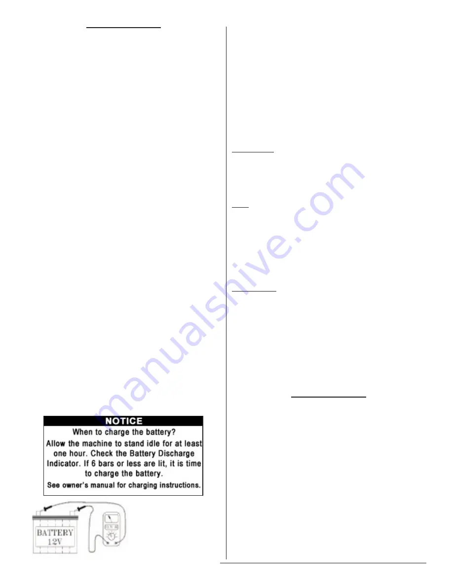
To measure the voltage, use a digital voltmeter (DC) on the 

battery poles.  The truck must not have been in use for the 

previous 30 minutes.

DANGER

Never alter the AC cord or plug provided. If it will not 

fit outlet, have proper outlet installed by a qualified elec

-

trician. Improper connection can result in a risk of an 

electric shock.

1. Disconnect the charger from the 115 volt wall outlet

once the indicators read fully charged.

Note:  The batteries are designed for intermittent use.  

Continual usage will wear the battery out and charging 

will be required.

E.  CHARGER OPERATION

Power Lamp
1. Green:  Connection correct.   Charger will operate nor-

mally.
2. Red:  Bad connection or bad battery.

Fault

1. Red light blinks 3 times in 5 seconds:  The output between

charger is faulty, loose, or bad connection
2. Red light blinks 5 times in 5 seconds:  The temperature

is too hot for the charger to operate.

3. Building power is not compatible; too low or too high.

+- 10% is the general rule.

Charge Lamp
1. Red:  Charger can charge normally.  The battery is less

than 70%

2. Orange:  Battery is between 70% and 100% charged.
3. Green:  Battery is at 100%.  Fully charged.
4. No light:  The charger can not charge the battery.  Voltage

of the battery may be too low to cause the charger to start.  It 

must be at 10.5 volts to initiate charge.

S E C T I O N  6

MAINTENANCE

Operation of Presto Power Stak is very simple — as is their 

construction.  They require very little maintenance.  Reason-

able care will result in excellent trouble-free performance. 

The Power Stak is designed for one-man operation and ease 

of performance.

Grease floor wheels and casters at least once a month.

Use only Hydraulic Oil AW32 or Dextron III in the

hydraulic system.

Do not 

overload your lift.

Check brakes, steering mechanisms and controls be-

fore each use.

VOLTAGE

Approx. 12.7 V .....  Fully charged
Approx. 12.2 V ........  1/2 charged
Approx. 12.0 V ........  1/4 charged
Approx. 11.6 V ........   Discharged

Summary of Contents for Power Stak PPS3000-125FS

Page 1: ...nual Model Number _____________________________________ Serial ____________________________________________ Date Placed in Service _____________ IMPORTANT READ CAREFULLY BEFORE INSTALLING OR OPERATING...

Page 2: ...ponsibility of the buyer and must be accompanied with an RGA number The shipping charge to return the component to the buyer is the responsibility of Presto Lifts Inc This limited warranty does not co...

Page 3: ...Checks 10 S E C T I O N 7 Troubleshooting 10 ORDERING REPLACEMENT PARTS 27 RESTOCKING POLICY 27 RETURN GOODS AUTHORIZATION 28 LIST OF FIGURES Fig 1 Operational Buttons 6 Fig 2 Straddle Leg 4 Bolt Tig...

Page 4: ...trial truck operator training into a search engine The battery operated stackers are very powerful lifts capable of doing large amounts of work DO NOT OPERATE THESE LIFTS WITHOUT CARE FULLY READING TH...

Page 5: ...load DO NOT operate when parts of anyone s body may be close to mast structure or any moving parts DO NOT drop loads on platform or forks DO NOT alter or modify this stacker in any way S E C T I O N 3...

Page 6: ...n the upper part of the handle When rotating the butterfly control CW towards the forks the stacker runs forwards in the forks first direction When rotating the butterfly CCW towards you the stacker r...

Page 7: ...area is clear of obstruc tions Check overhead clearance before lifting loads or trans porting B DAILY OPERATIONS MAINTENANCE CHECKS 1 Battery A Check for corroded and loose terminals A white powder su...

Page 8: ...N 1 Check general condition of Stacker loose or broken parts oil dangling wires dents cracked covers etc 2 Check metal frame mast carriage and font load supports for cracked welds worn or flat rollers...

Page 9: ...ord or plug provided If it will not fit outlet have proper outlet installed by a qualified elec trician Improper connection can result in a risk of an electric shock 1 Disconnect the charger from the...

Page 10: ...an and inspect all welds C Check wheels for wear and damage D Inspect nameplate for legibility Place the serial and model number shown on the nameplate on the cover of the manual for future reference...

Page 11: ...PRESTO OWNER S MANUAL Page 11 POWER STAK PPS3000 125FS PPS3000 125FS Figure 3...

Page 12: ...5FS PPS3000 125FS Exploded View Item Parts No Description Qty 1 1000 Body weld 1 2 2000 Mast assembly 1 3 3000 Lift mechanism 1 4 4000 Fork assembly 1 5 5000 Balance wheel 1 6 7000 Gear assembly 1 7 8...

Page 13: ...Snap ring 12 MM 4 5 2202 Guide roller 4 6 2203 Guide roller shaft 4 7 2204 Roller bearing 30706V 4 8 2205 Snap ring 30 MM 1 Item Parts No Description Qty 9 2103 Limit switch holder 1 10 2104 Limit sw...

Page 14: ...Qty 1 1101 Battery box cover 1 2 1102 Rear box cover 1 3 1103 Steering shaft cap 1 4 1104 Driving wheel cover 1 5 1201 Rear box 1 6 1202 Cover holder 1 7 1203 Battery holder 1 8 1204 Charger holder 1...

Page 15: ...Description Qty 1 3100 Lift frame 1 2 3200 Forged fork 2 3 3301 Fork shaft 1 4 3401 Idler wheel block 4 5 3402 Washer 4 6 3403 Snap ring 30 MM 4 7 3404 Roller bearing 30706V 4 8 3405 Bolt 4 9 3406 Nut...

Page 16: ...16 POWER STAK PPS3000 125FS Item Parts No Description Qty 1 4101 Leg assy 1 2 4102 Front wheel shaft 2 3 4103 Snap ring 35 MM 2 4 4201 Washer 4 5 4202 Ball bearing 6307 4 6 4203 Front wheel 2 PPS3000...

Page 17: ...lt M12X40 4 2 5102 Spring washer 12 MM 4 3 5103 Flat washer 12 MM 4 4 5104 Rear wheel frame 1 5 5201 Bolt M12X90 1 6 5202 Rear wheel side cover 2 7 5203 Snap ring 2 8 5204 Ball bearing 6203 2 9 5205 W...

Page 18: ...tion Qty 1 7100 Handle CH 2 1 2 7001 Handle pipe weld 1 3 7004 Pin 1 4 7002 Snap ring 8 MM 1 5 7003 Holder 2 6 7005 Air spring 1 7 7006 Bolt 1 8 7007 Flat washer 2 9 7008 Spring washer 1 10 7009 Lock...

Page 19: ...7103 Front button 1 4 7104 Electrical outlet big 1 5 7105 Electrical outlet small 1 6 7106 Left handle cover 1 7 7107 Handle top cover 1 8 7108 Spring 2 Item Parts No Description Qty 9 7109 Horn butto...

Page 20: ...5X50 3 13 7213 Spring washer 14 MM 1 14 7214 Gear Axle 1 15 7215 Key 8X7X18 1 PPS3000 125FS Drive Wheel Assembly Item Parts No Description Qty 16 7216 Ball Bearing 6006 2 17 7217 Gear 2 1 18 7218 Seal...

Page 21: ...18 UNF 1 2 8202 Bore 75 60 MM 1 3 8203 Nut M27x1 5 GB T 810 1988 1 4 8204 U CUPS Seals SUMPS 50x60x6 MM 2 5 8205 PTFE Ring 60 55 25 MM 1 6 8206 Piston 1 7 8207 Spacer 1 8 8208 Guide bush 1 9 8209 Wip...

Page 22: ...1 6 8106 Block 127x127 MM 1 7 8107 Flow control valve 1 8 8108 Relief valve 1 9 8109 Plug 1 10 8110 Tube 10 MM return 2 11 8111 Tube suction 1 Item Parts No Description Qty 12 8112 Fitting G3 8 19 2 1...

Page 23: ...PRESTO OWNER S MANUAL Page 23 POWER STAK PPS3000 125FS PPS3000 125FS Hydraulic Schematic Figure 15...

Page 24: ...PRESTO OWNER S MANUAL Page 24 POWER STAK PPS3000 125FS Labels Precautionary Warnings Figure 16...

Page 25: ...PRESTO OWNER S MANUAL Page 25 POWER STAK PPS3000 125FS August 2011 to Present Figure 17...

Page 26: ...N DIAG 24VDC SPECIFIED 8 PRESTO LIFTS DWG NO UNLESS OTHERWISE 80006 5 0 00 LB 1 1 DIMENSIONS ARE IN LIMITED TO WRITTEN AGREEMENT DR PowerStak TITLE SIZE CK A DWG NO FRACTIONS 1 XXX 005 XX 01 ANGLES 3R...

Page 27: ...pt parts covered by warranty Parts replaced under warranty are on a charge credit basis We will invoice you when we ship the replacement part then credit you when you return the worn or damaged part a...

Page 28: ...designs cannot be returned under any circumstances Presto Cus tomer Service reserves the right for final judgment on all product returns The RGA number must appear on the outside of any packaging mat...

Page 29: ...PRESTO OWNER S MANUAL Page 29 POWER STAK PPS3000 125FS LET PRESTO MEET THOSE NEEDS MANY NEEDS REQUIRE MANY OPTIONS...

Reviews: