16
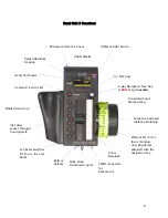
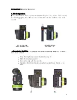
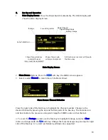
In situations where the lens setting must be controlled only by the single function hand
unit and not the HU3, the corresponding HU3 channel should be set to “Off”.
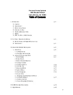
Zoom Mode Set-Up
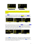
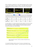
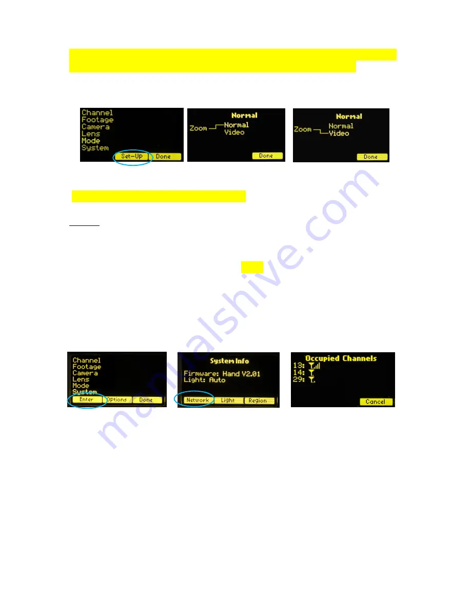
(Zoom modes are only supported for the MDR2) To choose a Zoom Mode press the
Set-Up
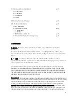
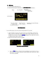
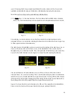
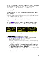
key (Fig. 7.5). The Normal Zoom mode (Fig. 7.6) means that the Hand Unit controls the
position of the zoom motor and this position is shown on the zoom bargraph display.
Limits can be set to the zoom range using the Set/Reset keys.
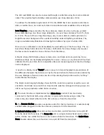
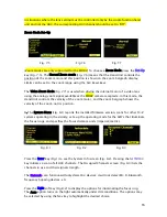
The Video Zoom Mode (Fig 7.7) is used when driving the internal motor of a video lens
using the analog zoom signal available at the MDR2 camera receptacle. In this mode, the
Hand Unit controls the velocity of the zoom motor, and the zoom bargraph shows the
velocity of the zoom, not its position.
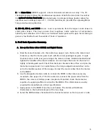
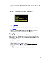
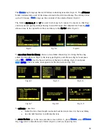
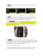
8. The System Menu (Fig. 8.1) reports the installed firmware version, scans for other FI+Z
systems operating in the vicinity, sets-up the operating mode for the LED’s that illuminate
the focus rings, and specifies the focus distance units (imperial/metric).
Press the
Enter
key (Fig.1) to see the System Info screen (Fig. 8.2). Pressing the
NETWORK
key initiates a scan of all HU3 channels. The Occupied Channels screen (Fig. 8.3) lists the
channels in use and their signal strength.
The
Network
scan function will only detect G4 devices; it will not detect Wi-Fi, Bluetooth,
frequency hopping devices, etc.
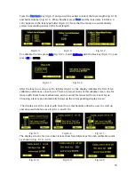
Press the
Light
soft key (Fig.8.2) to display the options for illuminating the focus ring.
The Auto option turns on the light automatically under dim conditions. The options may
be selected by using the Nav key to highlight the desired choice.
Fig. 8.1 Fig. 8.2 Fig. 8.3
Fig 7.6
Fig. 7.5
Fig. 7.7

