background image


25


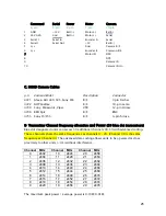
C. MDR3 Camera Cables 

 
p/n  Camera Model  


Description  

Connector 

4721  Alexa, Arri 435/535, Sony F65 

R/S 


3 pin Fischer


4722 

All 

Panaflex 

   R/S 

  10-pin 

Lemo 

4730  Sony, Panasonic, Viper 


VTR   


12-pin Hirose  

4746 

RED 

Epic    R/S 

  BNC 

4755 

Sony 

F5/F55 

   R/S 

  4-pin 

hirose 


D.


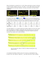
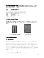
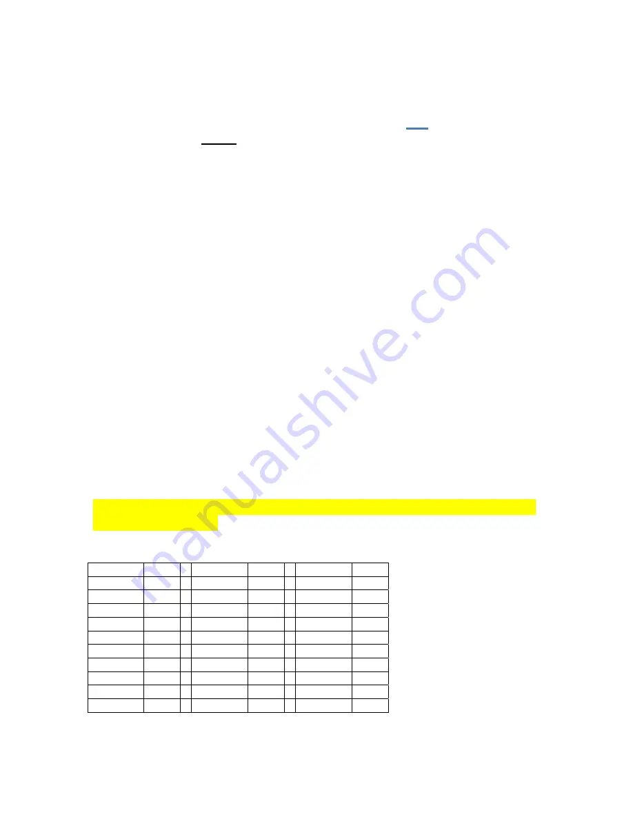
Transmitter Channel frequency allocation


and Power 

(G4 blue dot transceivers)


Blue dot designated units can access 30 additional channels 30-59 with advanced coding. 
These channels share the same frequencies as channels 0 – 29. (Channel 30 is the same 
frequency as Channel 0). The advanced data coding allows units to be operated at close 
proximity to other units (<1m) without interference. 
 

Channel MHz   Channel MHz 

Channel

MHz 

0 2402 

 10 2424

20 2458

1 2404 

 11 2428

21 2460

2 2406 

 12 2432

22 2462

3 2408 

 13 2436

23 2464

4 2410 

 14 2440

24 2466

5 2412 

 15 2444

25 2468

6 2414 

 16 2448

26 2470

7 2416 

 17 2452

27 2472

8 2418 

 18 2454

28 2474

9 2420 

 19 2456

29 2476

 
The maximum peak power / average power is 0.10W/0.01W. 


Command Serial Power  Motor 

Camera 

 6-pin 

4-pin  2-pin 

7-pin 

10-pin 

1 GND 

+12V  Batt(-) 

Motor(+) 

Batt(-) 

2 24V 

0.2A 

Gnd 

Batt(+) 

Motor(-) 

Serial 

Serial 1 

Serial In 


Encoder A 

Serial 

4 Serial1 

Serial 

Out 


+5V 

Batt(+) 

5 n/c 


 Gnd 

Camera 

R/S 

6 n/c 


Encoder B 

Common R/S 

7  


Motor 

ID 

DSR 


DTR 


Camera 

ID 

10   


Camera ID rtn 


Summary of Contents for F I + Z

Page 1: ...F I Z Lens Control DRAFT Rev 4 02 ...

Page 2: ...and Unit 3 p 5 III Hand Unit Detailed Description p 8 A Hand Grip p 8 1 Configurations 2 Changing the hand grip B HU3 Set Up and Operation p 9 1 Main Display p 9 2 Menu Screen 3 Radio Channel Selection 4 Footage Counter 5 Camera Selection p 10 6 Lens Set Up p 10 7 Operating Mode p 13 8 System Menu p 15 9 Zoom Bargraph P 16 10 Lens Limits 11 Panatape and Cinetape interfaces 12 Software Updates p 17...

Page 3: ...tion has been paid to protecting the unit from impact and environmental damage The microwave antenna is integrated within a form fitting cover The iris slider uses a magnetic sensor to eliminate the opening required for a conventional sliding seal The soft urethane handgrip and focus knob cover not only provide for comfortable all day operation but also protect the unit from shock Generation 4 G4 ...

Page 4: ...en calibrated to the unit Data from compatible ultrasonic measuring devices like the Cinetape can be displayed A new focus display mode Marks gives an easy to interpret bargraph representation of the difference between the distance set by the focus knob and reference marks entered by the user Multiple reference marks can be set by entering their position with a soft key located below the display T...

Page 5: ...t the motor gears mesh with the corresponding lens gears Couple the lens motors to the lens gears Adjust the motors to have minimum backlash and tighten the handles of the motor brackets Do not couple the motor to the lens too tightly or binding will result Check that the motor brackets do not flex or slip on the matte box support rods For normal lenses the torque adjustment switches can be set in...

Page 6: ...Host will appear in the upper left corner of the display replacing the ft and fps text d Match the HU3 wireless channel to the MDR Press the Menu soft key Channel will be highlighted Use the Nav key to move the selection to the right Change the channel number with the Nav key to match the setting of the MDR Menu Screen Channel Selection Main Display Screen Lens Selection Shows focus distance in di...

Page 7: ...ly mark separate rings for each lens Data from the lens library is matched to pre printed focus marking rings This makes process of lens changing quick and efficient A detailed description of this function showing the display screens is given in section III To load focus data for a lens and select a focus ring Press the Menu key Use the Nav key to select Lens Press Choose Select the lens location ...

Page 8: ...focus marking ring Brightness adjusted with the navigation key Molded Hand Grip Zoom Bargraph Iris Slider senses through housing wall Splash Resistant Housing Hand Unit Power Camera R S with LED 4 way Navigation Nav Key Enter key in center 3 x Soft Keys Neck Strap Attachment point Set Reset switches for Focus Iris and Zoom LEMO receptacle for Remote Iris Battery Release ...

Page 9: ...ket and Micro Force zoom control 2 Removing the Hand Grip The Handgrip is removed to allow the bracket for the Micro Force to be installed Press the Grip Release toward the HU3 housing 1 Slide the Grip downward 2 Replace the Grip with the cover 3 Install the Micro Force bracket using the threaded hole at the rear of the HU3 HU3 with Hand Grip and Quick Release Plate HU3 with Micro Force and bracke...

Page 10: ...ntenna icon and bars indicate the presence and signal strength of MDR3 units on that channel 4 To reset the Footage counter use the Nav key to highlight Footage and press Clear Units are changed with the ft m soft key Change the movement type by pressing the right side of the Nav key 4 3 and 2 perforation pull down are supported Lens Selection Shows focus distance in digital format Lens must be ca...

Page 11: ...n Press the Set Up key to bring up the camera Control menu Fig 5 4 Use the Nav key to select and then modify the camera speed and shutter angle The List key appears when editing either a camera speed or shutter angle Pressing this key brings up tables containing commonly used camera speeds and shutter angles Fig 5 5 Fig 5 6 6 Selecting Lens with the Nav key Fig 6 1 allows lenses to be calibrated a...

Page 12: ...der fig 6 3 To use a lens from the library choose a lens folder shown Fig 6 4 Using the Nav key select the manufacturer fig 6 5 the lens type fig 6 6 and the lens fig 6 7 and press either OK or ENTER Use the focus knob to set the lens to infinity Fig 6 8 and press NEXT ENTER The lens name now appears on the main screen Fig 6 9 To calibrate a new lens Name the lens focal length and serial number an...

Page 13: ...finity Fig 6 14 the display indicates the first of ten calibration distances close focus There are two versions of this display screen one for lenses with linear focus mechanisms and a second for lenses with non linear focus Choosing a lens type automatically brings up the corresponding display screen The display screen for lenses with linear focus mechanisms allow the user to scroll up and down w...

Page 14: ...d in imperial and metric units The printed labels Ai Ei are pictured below Note that the midpoint of each scale is about twice the minimum focus distance Although the ring can be chosen to cover the entire focus range of the lens it is often advantageous to choose the ring which covers the minimum focus required for the actual shooting For example the Summilux 18mm lens has an 18 near focus matchi...

Page 15: ...cus iris or zoom or the Focus Iris control focus or iris or the Radio Micro Force zoom Use the Navigation key to scroll down to AUX Press the right side of the NAV key and a select the source for the AUX channel to track Figure 7 3 shows the AUX tracking the HU3 iris The second function of Custom Mode is to turn off one or more of the HU3 control channels focus iris zoom or auxiliary This is usefu...

Page 16: ...rgraph shows the velocity of the zoom not its position 8 The System Menu Fig 8 1 reports the installed firmware version scans for other FI Z systems operating in the vicinity sets up the operating mode for the LED s that illuminate the focus rings and specifies the focus distance units imperial metric Press the Enter key Fig 1 to see the System Info screen Fig 8 2 Pressing the NETWORK key initiate...

Page 17: ...nnected to the HU3 as the zoom position is only available when a digital motor and Y cable are used The zoom bargraph indicates the lens limits as described in the next section 10 Lens Limits Fig 10 1 can be set using the three groups of set reset s r keys To set a limit move the motor to the first limit and press the set s key While keeping the s key pressed move the motor to the second limit and...

Page 18: ...default display Fig 11 3 11 Software updates can be downloaded from the website http www prestoncinema com downloads html To load an update into the HU3 Install the boot loader program from the downloads page Make sure that the Hand Unit is not powered Connect the serial cable 4538 serial connector to 4 pin Lemo between the serial port of the pc and the Serial receptacle on the rear cover of the H...

Page 19: ... 13 Focus Ring Light Under low light conditions two white LED s will automatically illuminate the Focus Ring To Change the brightness of the LED s tap the top bottom of the Nav key to increase decrease the brightness level IV MDR3 Detailed Description Fig 12 1 Remote Iris Box p n 4020 MDR3 Torque and Direction Switches Input Output Connectors MDR3 Channel Display Switches Top Channel Display Switc...

Page 20: ...ing connector The bottom row of buttons controls the torque and the upper row controls the direction At each press of the torque button the LED color changes to indicate the maximum torque level blue minimum green mid level red maximum Pressing the direction button changes the motor direction to correspond with the Hand unit The white LED indicates the status After approximately 4s from the last b...

Page 21: ...he focus ring of cinema lenses The DM 2 is a smaller and lighter weight motor It is recommended for driving the zoom and iris of all lenses and the focus for all but very stiff lenses The DM 1X and DM 2 are available with an integral bracket the A version This bracket provides for simplified mounting and also allows the motors to be positioned very close to one another A rosette gear securely lock...

Page 22: ...wing arm clamps to 19mm rods Step down bushings accommodate 15mm and 0 635 rods p n 4320 and p n 4321 respectively All of the brackets have one 15mm opening for the motor rod and one 19mm opening for a matte box rod A step down bushing is required for 0 625 Panavision rods or 15mm Arri rods Bracket p n Distance between holes Use 4310 2 2 PV top rod bracket 4334 1 6 Clamps to PV Long Rod Support br...

Page 23: ...h the limits for a class B digital device pursuant to part 15 of the FCC Rules These limits are designed to provide reasonable protection against harmful interference in a residential installation This equipment generates uses and can radiate radio frequency energy and if not installed and used in accordance with the instructions may cause harmful interference to radio communications However there...

Page 24: ...vice complies with Part 15 of the FCC Rules Operation is subject to the following two conditions 1 This device may not cause harmful interference and 2 This device must accept any interference received including interference that may cause undesired operation FCC RF EXPOSURE STATEMENT To satisfy RF exposure requirements this device and its antenna must operate with a separation distance of at leas...

Page 25: ... The advanced data coding allows units to be operated at close proximity to other units 1m without interference Channel MHz Channel MHz Channel MHz 0 2402 10 2424 20 2458 1 2404 11 2428 21 2460 2 2406 12 2432 22 2462 3 2408 13 2436 23 2464 4 2410 14 2440 24 2466 5 2412 15 2444 25 2468 6 2414 16 2448 26 2470 7 2416 17 2452 27 2472 8 2418 18 2454 28 2474 9 2420 19 2456 29 2476 The maximum peak power...

Reviews: