background image


H

H

a

a

n

n

g

g

z

z

h

h

o

o

u

u


P

P

r

r

e

e

v

v

a

a

i

i

l

l


O

O

p

p

t

t

o

o

e

e

l

l

e

e

c

c

t

t

r

r

o

o

n

n

i

i

c

c


E

E

q

q

u

u

i

i

p

p

m

m

e

e

n

n

t

t


C

C

o

o

.

.

,

,


L

L

t

t

d

d

.

.


1.


Product Summary   

WR1002RJL

 is our latest high-end two-way output CATV network optical receiver. The pre-amp 

adopts  full  GaAs  MMIC  amplify  module  and  the  post-amp  adopts  GaAs  amplify  module. 
Optimization  circuit  designs,  coupled  with  the  company  10  years  professional  design  experience, 
make  the  equipment  achieve  high  performance  index.  The  parameters  will  be  displayed  by 
singlechip to make the engineering debug more convenient. It is the best choice for CATV network. 

2.


Performance Characteristics   

WR1002RJL 

WR1002RJL-1G 

Optical Receiver 

Manual


Summary of Contents for WR1002RJL

Page 1: ...e amp adopts full GaAs MMIC amplify module and the post amp adopts GaAs amplify module Optimization circuit designs coupled with the company 10 years professional design experience make the equipment achieve high performance index The parameters will be displayed by singlechip to make the engineering debug more convenient It is the best choice for CATV network 2 Performance Characteristics WR1002R...

Page 2: ...cal node used in CATV systems and tested in the following conditions Test conditions 1 Forward optical receive part with 10km standard optical fiber passive optical attenuator and standard optical transmitter composed the testing link Set 59 PAL D analog TV channel signal at range of 45 87MHz 550MHz under the specified link loss Transmit digital modulation signal at range of 550MHz 862 1003MHz the...

Page 3: ...Output Level dBμV 114 Output Return Loss dB 14 Output Impedance Ω 75 Electrical control EQ range dB 0 10 Electrical control ATT range dB 0 20 Reverse Optical Transmit Part Optical Parameters Optical Emission Wavelength nm 1310 10 1550 10 or specified by the user Output Optical Power mW 0 5 1 2 Optical Connector Type FC APC SC APC or specified by the user RF Parameters Frequency Range MHz 5 65 or s...

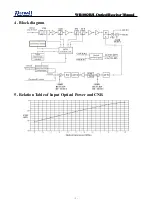
Page 4: ...R1 1 10 0 00 0 02 2 2R R RJ J JL L L O O Op p pt t ti i ic c ca a al l l R R Re e ec c ce e ei i iv v ve e er r r M M Ma a an n nu u ua a al l l 3 4 Block diagram 5 Relation Table of Input Optical Power and CNR ...

Page 5: ...l l R R Re e ec c ce e ei i iv v ve e er r r M M Ma a an n nu u ua a al l l 4 6 Function Display and Operating Instruction Mode Mode selection button up button increase the value of parameters down button decrease the value of parameters The following is the detailed instructions ...

Page 6: ...work the image of the optical contact point has obvious netlike curve or large particles highlights but the image background is clean 1 The input optical power of the optical receiver is too high make the output level of the optical receiver module too high and RF signal index deteriorate 2 The RF signal input the optical transmitter index is poor 1 Check the input optical power and make appropria...

Page 7: ...intrusion 1 Check if there is strong interference signal source change the optical contact point location if possible to avoid the influence of strong interference signal source 2 Check the cable lines of the optical contact point if there is shielding net or situation that the RF connector shielding effect is not good 3 Tightly closed the equipment enclosure to ensure the shielding effect if poss...

Page 8: ...ed so as to avoid hurting inside fiber 6 Use compressed air or degrease alcohol cotton to wash the adapter carefully When use compressed air the muzzle aims at china tube of the adapter clean the china tube with compressed air When use degrease alcohol cotton insert directions need be consistent otherwise can t reach a good clean effect 10 After sales Service Description 1 We promise Free warranty...

Reviews: